
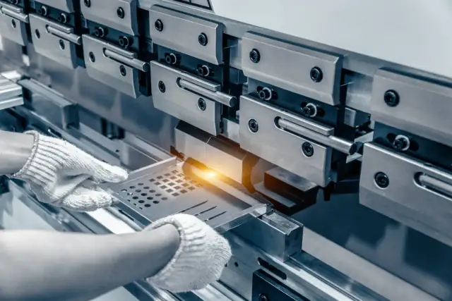
PrecisionSheet Metal Bending
Press brake forming for brackets, enclosures, channels, and formed sheet metal components. Controlled bend radii, predictable springback compensation, and repeatable angles—built for prototypes and scalable production.
Angle Control
±0.5° (typ.)
Fast-Track
3–7 Days
Gauge Range
Typically 26 ga–1/4"
In-house process
Bending, deburring, and inspection under one roof.
Sheet Metal Bending Services
Engineering-First Press Brake Forming for Consistent Bends
PREMSA delivers sheet metal bending built around repeatability: controlled inside radius, stable bend allowance (K-factor), and consistent angles across the batch. We review your flat pattern intent early to prevent scrap from missing bend reliefs, incorrect bend deductions, or feature conflicts near bends.
Our approach is grounded in real press brake constraints: minimum flange lengths, V-die selection, punch radius, springback behavior by alloy/temper, and grain direction effects. We focus on getting you formed parts that assemble correctly—without surprise rework.
From rapid prototypes to production runs, PREMSA supports multi-bend sequencing, optional deburr/edge break, and fit-driven inspection. We prioritize the dimensions that matter: flange-to-flange, hole-to-bend, overall formed envelope, and interface geometry.
What is Sheet Metal Bending?
Sheet metal bending is a forming process that shapes flat sheet into 3D parts by applying force along a bend line—most commonly on a press brake using a punch and V-die. The final geometry is governed by inside bend radius, bend angle, material thickness, and bend allowance/deduction.
It is ideal for brackets, channels, enclosures, stiffeners, covers, and formed panels where consistent angles, repeatable flanges, and predictable fit-up are required.
The Forming Workflow
An engineering-driven process designed to control bend accuracy, springback, and repeatability for formed sheet metal parts.
1. File Intake & Requirements
We receive drawings and flat patterns (or models) and confirm material, thickness/gauge, quantities, grain direction requirements, and any cosmetic or functional constraints.
2. Drawing & Flat Pattern Validation
We validate units, revision control, bend notes, critical-to-quality (CTQ) dimensions, datums, and formed envelope requirements before tooling and setup.
3. Bend Feasibility (DFM)
We review minimum flange lengths, bend relief needs, hole/slot proximity to bends, and interference risk across the bend sequence.
4. Tooling & Method Selection
We select punch radius and V-die opening based on thickness and target radius/angle—air bending, bottoming, hemming tools, or specialty setups as required.
5. Bend Allowance / Deduction Setup
We set bend allowance/deduction using K-factor or empirical tuning to match the real material behavior and meet formed dimensions.
6. Setup, First-Article & Angle Tuning
A first piece is formed and measured to tune angle and formed dimensions. Springback compensation is applied based on alloy/temper and bend length.
7. Production Forming & Sequencing
Parts are formed using a controlled sequence to avoid collisions and to keep angles consistent across the batch.
8. Inspection & Release
CTQ dimensions and angles are verified using calibrated tools (angle gauges, height gauges, CMM when needed). Parts are released after meeting requirements.
Press Brake Tooling & Setup
Punch Radius Selection
Choose punch radius based on material thickness and required inside radius to reduce cracking, minimize marking, and keep bend geometry predictable.
V-Die Opening (V-width)
Die opening drives tonnage, achievable inside radius, and angle stability. Wider V reduces tonnage but increases radius; tighter V increases tonnage and control.
Air Bend vs. Bottoming vs. Coining
Method selection is tooling-driven: air bending is flexible, bottoming improves repeatability, and coining tightens angle/radius control when CTQ requirements justify it.
Gooseneck & Clearance Tooling
Clearance punches (gooseneck/offset) prevent collisions on return flanges and complex geometries, enabling multi-bend parts without deforming formed features.
Hemming, Flattening & Special Tooling
Hemming tools, flatteners, and specialty punches support edge folds and formed details. Tool choice depends on material, thickness, and cosmetic requirements.
Backgauge Strategy & Repeatability
Backgauge selection and gauging surfaces are chosen to control flange lengths and bend-to-feature locations. Stable references reduce stack-up error across batches.
Technical Advantages
Repeatable Angles & Flanges
Controlled tooling and springback compensation improve angle consistency across production batches.
Predictable Fit-Up
Bend allowance/deduction control helps deliver formed dimensions that assemble correctly with mating parts.
Process Matched to Requirements
Air bending, bottoming, or specialty setups are selected based on CTQ needs—avoiding unnecessary cost drivers.
Robust DFM for Bent Features
Early review prevents tear-out, distortion, and feature conflicts near bends that commonly cause scrap.
Efficient Throughput
Standardized setups and bend sequencing keep lead times predictable from prototypes to production.
Inspection Aligned to Assembly
Verification focuses on flange-to-flange, hole-to-bend, and formed envelope dimensions that drive real-world fit.
Bending Capacity & Envelope
Part Envelope
Maximum formable envelope depends on bend geometry, tooling, and required tonnage. Large parts may be reviewed case-by-case.
Reviewed case-by-case
Gauge / Thickness Range
Supported range depends on material type and required bend radius/angle control. Very thick plate bending may require special tooling.
Typically 26 ga – 1/4"
Bend Detail Capability
Minimum flange lengths, inside radius targets, and feature proximity limits are driven by tooling and material behavior.
DFM-driven per geometry
Tight Angles or Dense Features Near Bends?
If your parts include short flanges, holes close to bend lines, tight inside radii, or cosmetic faces, request a bend feasibility review before release.
Tolerances & GD&T
Formed accuracy depends on material, thickness, bend length, inside radius, and springback behavior. Defining critical-to-quality (CTQ) dimensions (angles, flange lengths, hole-to-bend) helps control cost while protecting fit and function.
| Category | Technical Capability | Engineering Notes |
|---|---|---|
| Angle & Formed Dimension Control | Angle accuracy and formed dimensions depend on material type/temper, bend length, tooling selection, and springback compensation. Tight requirements may require additional setups or verification. | Call out CTQ angles and flange dimensions only where needed. Over-constraining all bends increases cost without improving fit. |
| Inside Radius, Minimum Flange & Feature Limits | Minimum flange lengths and achievable inside radii are governed by punch radius, V-die opening, and material thickness. Features too close to bends may distort or cause tearing. | Avoid placing holes/slots too close to bend lines. Use bend reliefs and respect minimum flange guidelines for stable forming. |
| Springback, Distortion & Grain Direction | Springback varies by alloy and temper and can shift final angles. Grain direction affects cracking risk and consistency, especially on tighter radii. | Specify grain direction only when it’s functionally required. Tight radii on hard tempers may require radius adjustments. |
| Inspection & Verification | Inspection focuses on CTQ features such as angles, flange-to-flange dimensions, hole-to-bend, and formed envelope using calibrated gauges and fixtures as appropriate. | Provide datums, bend notes, and CTQ callouts to align inspection to real assembly interfaces. |
Sheet & Plate Materials
Choose from production-grade metals and cuttable non-metals. Material selection impacts bendability, edge quality, corrosion resistance, electrical performance, and cosmetic finish.
Metals (Sheet / Plate)
Non Metal Materials
Surface Finishes
Surface finishing improves corrosion resistance, wear life, and cosmetic appearance. Finishes should be selected based on environment, assembly requirements, and long-term durability.
Finish Options
Sheet Metal Bending DFM Guidelines (DFM)
Bend manufacturability is driven by inside radius, bend relief, minimum flange length, feature proximity to bends, and springback behavior. Following these DFM rules reduces scrap, protects cosmetics, and improves repeatability in production.
| Design Feature | Recommendation |
|---|---|
| Bend Reliefs & Corner Treatments | Use bend reliefs to prevent tearing at corners and to control deformation near bend intersections. Corner treatments help avoid tear-out and improve cosmetic consistency. |
| Holes/Slots Near Bends | Keep holes and slots away from bend lines to avoid distortion and ovalization. If features must be close, plan for larger edge distance, alternate bend sequence, or secondary ops. |
| Bend-to-Feature & Feature Spacing | Maintain adequate spacing between bends and nearby features to protect flatness and accuracy. Dense patterns near bends can shift during forming due to material flow. |
| Datums, Alignment Tabs & Part ID | Use clear datums for formed dimensions and consider alignment tabs/slots only when they support assembly. Part identification should be placed away from cosmetic faces and bend zones. |
| PEM Hardware, Threads & Secondary Operations | Plan hardware insertion and threading intentionally. Many designs benefit from installing PEM nuts/studs after forming, and specifying secondary drilling/tapping where required. |
| Drawing & Flat Pattern Checklist | Provide formed dimensions, bend angles, inside radius targets (or tooling notes), material/gauge, grain direction (if required), and CTQ callouts. Flat pattern should reflect correct bend allowance/deduction intent. |
Applications & Industries
Sheet Bending Applications
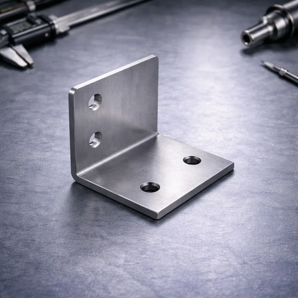
Brackets & Mounts
Formed brackets with controlled angles and repeatable hole-to-bend geometry for reliable fit-up.
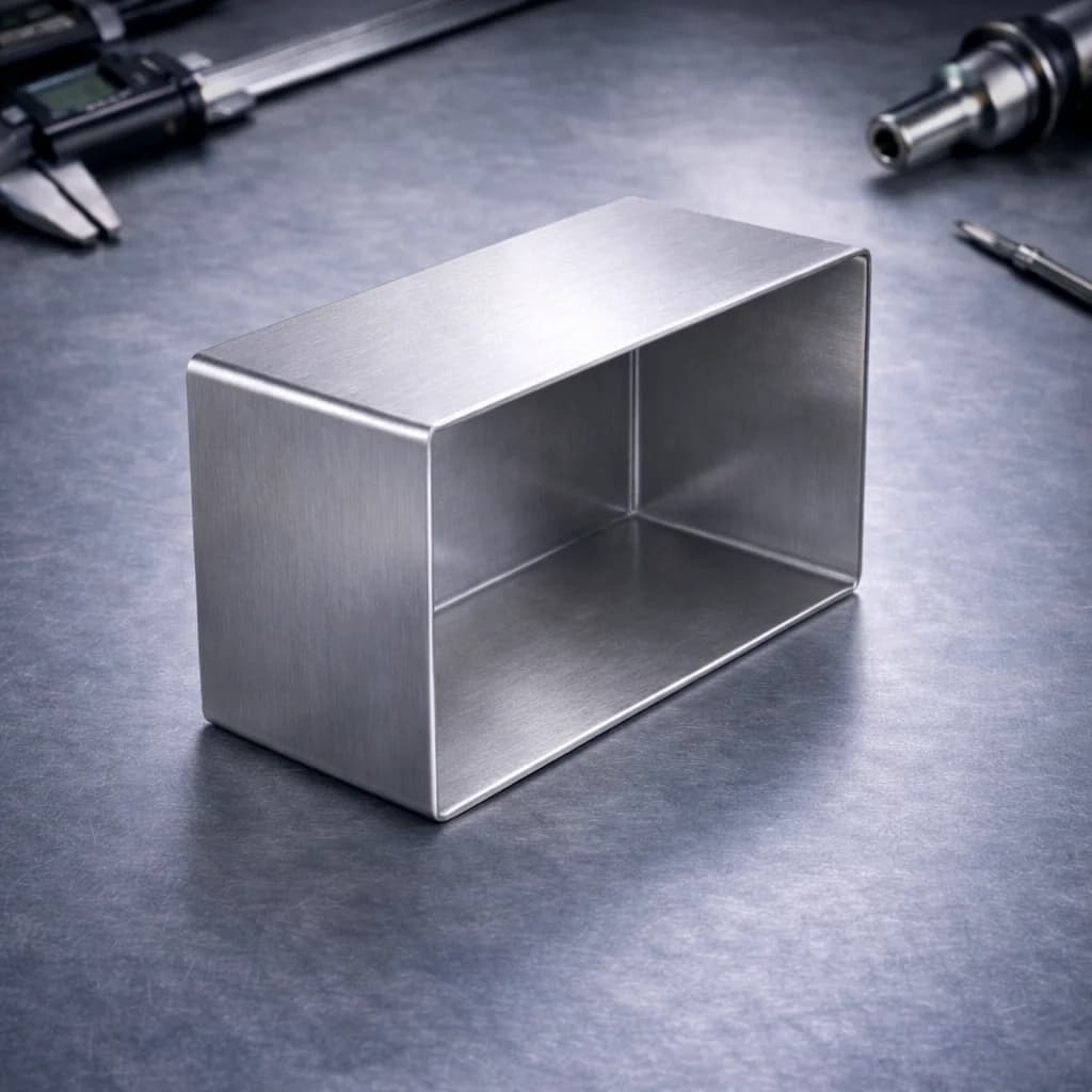
Enclosures, Covers & Panels
Press-brake formed panels and covers for electrical and industrial enclosures requiring durable geometry and cosmetics.
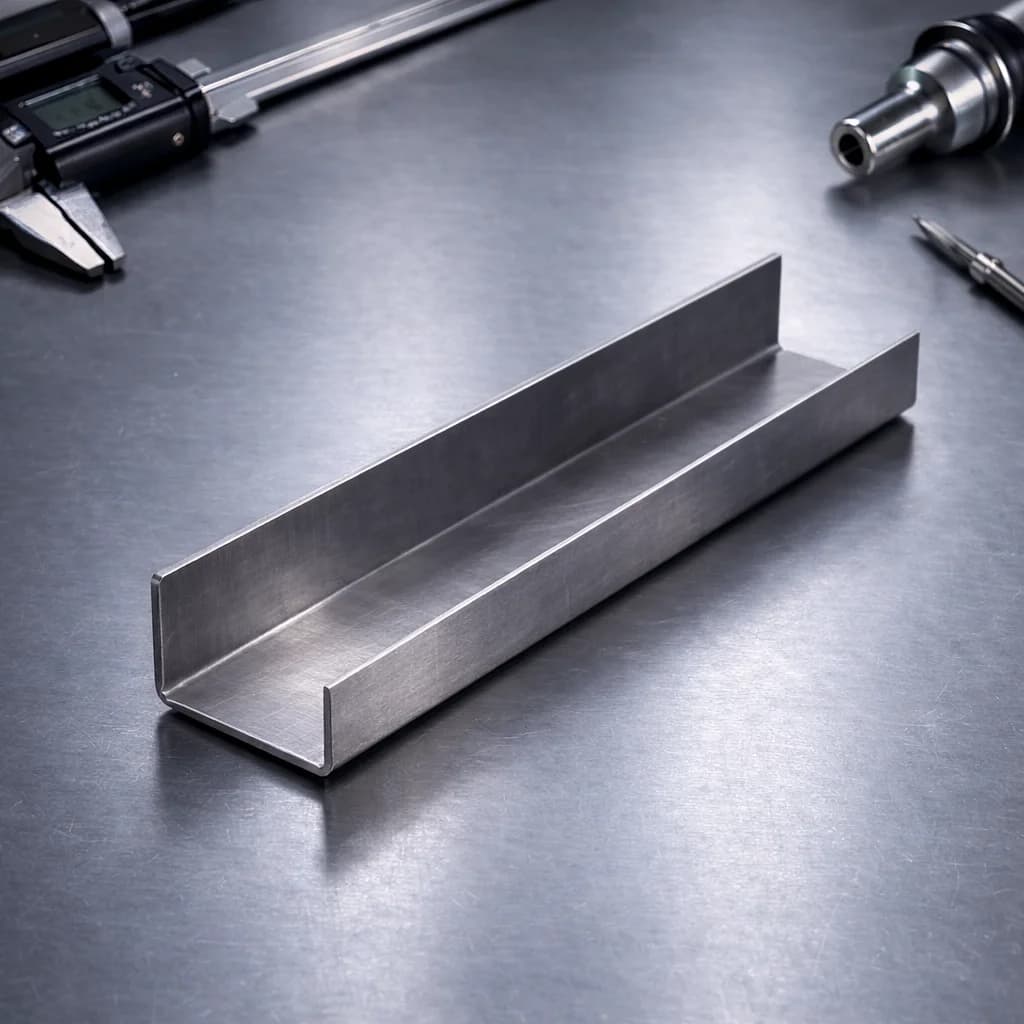
Channels, Trays & Frames
Multi-bend components such as channels and trays designed for stiffness, routing, and modular assembly.
Sheet Bending Industries
Lighting
Formed sheet metal housings, reflectors, brackets, and structural components used in commercial and architectural lighting systems.

Hardware
Precision bent brackets, structural supports, and formed sheet metal components used in mechanical hardware and equipment assemblies.

Industrial
Press-brake formed panels, machine covers, guards, and frames designed for durability and repeatable production environments.

FAQs & Knowledge Base
Sheet Bending FAQs
Sheet metal bending services
Press-brake bending turns flat blanks into structural sheet parts: brackets with flanges, U-channels, boxes, and complex multi-bend profiles. PREMSA aligns bend sequences, tooling selection, and springback control to hit angle and dimension targets on production runs.
See sheet metal fabrication for full cut-and-form programs and the CNC design guide for bend-friendly CAD practices.
PREMSA ecosystem
Services, guides, and tools for sheet metal bending
We operate from Monterrey for engineering teams across Mexico and North America. We deliver press-brake forming with DFM for bend radii and reliefs with ISO 2768 tolerances, engineering materials, and prototype-to-production routes. Use the technical references below and quote online with STEP or STL files.
Metal fabrication processes
Engineering tools
- Interactive chart
ISO 2768 Tolerance Chart
Look up general linear and geometric tolerances for sheet metal and machined features.
View chart - Calculator
Tap Drill Size Calculator
Calculate tap drill sizes for PEM inserts, threaded holes, and formed features.
Open tool - Reference chart
Drill Bit Size Chart
Reference drill diameters for clearance holes and hardware prep in fabricated assemblies.
View chart
- What files should I upload for sheet metal bending?
- Upload a 2D drawing (PDF) with formed dimensions and bend notes, plus a flat pattern (DXF) or 3D model. Include material/gauge, inside radius targets (or tooling notes), and CTQ callouts like flange-to-flange and hole-to-bend.
- How do you control bend angles and springback?
- Angle control is achieved through tooling selection, brake setup, and springback compensation based on alloy/temper and bend geometry. A first-article check is used to tune angles before running the batch.
- Can you form short flanges or tight radii?
- Short flanges and tight radii depend on thickness, material, and tooling. We review feasibility using minimum flange and inside radius guidelines and may recommend bend reliefs or alternate design strategies.
- What dimensions should be toleranced on bent parts?
- Tolerance the dimensions that drive assembly: angles, flange lengths, flange-to-flange, and hole-to-bend. Avoid over-tolerancing every bend; it increases cost without improving function. Reference our ISO 2768 chart, tap drill calculator, and drill bit size chart when specifying holes and threads.
- Do you support finishing after bending?
- Yes, when specified. Common options include deburr/edge break, powder coating, zinc plating, anodizing (aluminum), and passivation (stainless). Finish selection should match corrosion and cosmetic needs.
- What drives cost the most in sheet metal bending?
- Primary drivers include material/gauge, number of bends, bend length, complexity of bend sequencing, tight angle/formed tolerances, cosmetic protection requirements, and any secondary operations or hardware insertion.
Ready for your next project with PREMSA?
Upload your STEP file, set material and quantity, and get DFM review with clear lead times and an online quote.