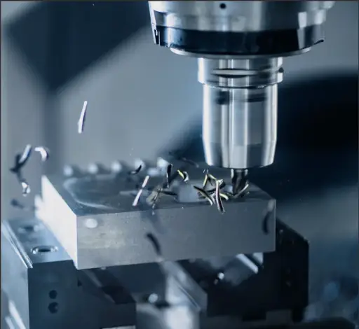
Custom CNCMilling Services
3, 4 & 5-axis CNC milling for prismatic parts, tight tolerances, and production-ready repeatability—optimized by manufacturing engineers.

Precision
±0.001"
Lead Time
3–5 Days
Volumes
1–10k+ Pcs
In-House Process
CNC milling and dimensional inspection performed in-house.
CNC Milling
Why Choose PREMSA for Custom CNC Milling
PREMSA delivers precision CNC milling services built for engineers who need tight tolerances, repeatable geometry, and dependable lead times. We machine production-grade metals and engineering plastics from your CAD data, with clear communication on manufacturability, cost drivers, and inspection requirements.
Our CNC milling workflow is engineering-driven: we validate critical features, confirm datums and GD&T intent, and recommend practical changes that reduce cycle time without sacrificing performance. This approach minimizes revisions, prevents tolerance stack-up issues, and improves first-pass yield for complex milled components. You can also use our ***CNC Machining Guidelines***(/resources/guides/cnc-machining-design-guidelines) to standardize DFM criteria and reduce rework from the design stage.
From rapid CNC milling prototypes to scalable production, PREMSA supports consistent quality with documented processes, optional material certifications (MTR/CoC), and inspection reporting. Customers choose PREMSA for CNC milling because we deliver manufacturable solutions—accurate parts, predictable outcomes, and technical accountability.
What is CNC Milling?
CNC milling is a subtractive manufacturing process that uses rotating cutting tools to remove material from a solid block or plate and create precise 3D features. A CNC mill follows programmed toolpaths to machine pockets, slots, contours, holes, and planar surfaces with controlled tolerances and repeatable results.
Engineers use CNC milling for functional, production-grade parts that require high accuracy, strong material properties, and clean surface finishes. CNC milling is ideal for prismatic components, complex housings, fixtures, brackets, manifolds, and multi-face parts that benefit from 3-axis, 4-axis, or 5-axis machining strategies.
How CNC Milling Works
A practical workflow from CAD to finished milled parts—optimized for accuracy, cost, and lead time.
1. CAD Review & DFM
We review your 3D model and drawings to confirm datums, critical tolerances, wall thickness, internal radii, and tool access. This DFM step identifies risk areas early and aligns machining strategy with functional intent.
2. CAM Programming
Our engineers select tools and create optimized toolpaths for roughing, semi-finishing, and finishing based on material, feature depth, and surface finish (Ra) requirements. Programming choices directly impact cost-per-part and repeatability.
3. CNC Milling Operation
Parts are machined on calibrated CNC milling centers using controlled feeds/speeds and rigid workholding. Multi-axis setups reduce repositioning, improving geometric accuracy and minimizing tolerance stack-up.
4. Inspection & Verification
Critical dimensions are verified with appropriate metrology—calipers, height gages, optical tools, or CMM inspection. We can provide inspection reports and certification documentation when required.
Types of CNC Mills
3-Axis CNC Milling
The most common CNC milling setup for flat and prismatic parts. Best for pockets, slots, hole patterns, and planar features. Cost-effective for prototypes and production when features are accessible from standard orientations.
4-Axis CNC Milling (Indexed or Continuous)
Adds a rotary axis to machine multiple faces with fewer setups. Improves positional accuracy and reduces handling for parts requiring features around a circumference or multi-side machining.
5-Axis CNC Milling
Enables complex contours, angled features, and tight-tolerance multi-face machining in fewer setups. Ideal for aerospace surfaces, impellers, complex brackets, and parts where geometric precision and surface quality are critical.
Benefits of CNC Milling
High Accuracy & Repeatability
CNC milling produces consistent parts with predictable tolerances, making it ideal for assemblies, precision interfaces, and repeat production orders.
Production-Grade Materials
Machine real engineering metals and plastics—aluminum, steel, stainless, titanium, acetal, PEEK, and more—maintaining material integrity for end-use applications.
Complex Features in Fewer Setups
Multi-axis CNC milling reduces repositioning, improves geometric accuracy, and helps control true position, perpendicularity, and profile tolerances on multi-face parts.
Controlled Surface Finish Options
Achieve functional and cosmetic finishes with specified roughness (Ra), bead blasting, anodizing, plating, and other secondary operations tailored to your application.
Fast Prototyping to Scalable Production
CNC milling supports rapid iteration for prototypes and reliable scaling for low-to-mid volume manufacturing—without the cost and lead time of hard tooling.
DFM-Driven Cost Optimization
Practical DFM feedback—like increasing internal radii, reducing deep pockets, and limiting tight tolerances to critical features—can significantly lower cycle time and unit cost.
Work Envelope & CNC Milling Capabilities
Maximum Part Size
CNC milling work envelope supported across 3-axis, 4-axis, and 5-axis platforms. Suitable for large prismatic components, multi-face machining, and complex fixturing where dimensional alignment across multiple planes is required.
40" x 20" x 20"
Minimum Feature Size
Minimum achievable feature size in CNC milling depends on material properties, cutter diameter, tool reach, and part rigidity. Fine features, thin walls, and tight internal radii are evaluated through DFM to ensure machining stability and repeatability.
±0.001" / 0.005" Rad
Batch Sizes & Volumes
CNC milling capacity supports everything from single-part prototypes to repeat production programs. Process documentation and inspection strategies scale with volume to maintain consistent quality.
1 – 10,000+ Parts
Exceeding these limits?
Non-standard part sizes, geometries, or machining constraints are reviewed regularly. Upload your CAD for a custom CNC milling engineering assessment.
CNC Milling Tolerances & GD&T
CNC milling tolerances and GD&T definitions directly influence machining strategy, setup planning, and inspection methods. Clearly identifying critical features enables proper tool selection, datum alignment, and repeatable results across multi-axis milling operations.
| Category | Technical Description | Typical Notes |
|---|---|---|
| Standard CNC Milling Tolerances | Standard tolerances commonly achieved in CNC milling without special environmental control or custom fixturing. Typical defaults include ±0.005" or ISO 2768-m for prismatic, multi-face milled components. | Apply standard tolerances wherever possible to reduce setup complexity and machining time. |
| Tight & Precision Milling Tolerances | Tolerances down to ±0.001" are achievable with stable datums, rigid workholding, controlled cutting forces, and optimized finishing strategies during CNC milling. | Restrict tight tolerances to functional features to control cost and inspection effort. |
| Threads & Tapped Holes | Threaded features produced via CNC milling and tapping in accordance with ASME (UNC/UNF) or ISO metric standards. Thread depth and class selection impact tool life and cycle time. | Specify thread standard, class, depth, and preferred method (thread milling or tapping). |
| Surface Finish (Ra) | Surface roughness in CNC milling is controlled by cutter geometry, step-over, spindle speed, and finishing passes. Typical as-milled surfaces range from Ra 125 to Ra 32, with finer finishes achievable on accessible features. | Call out Ra only on functional or cosmetic surfaces to avoid unnecessary finishing operations. |
| Inspection & GD&T Verification | Verification of milled features and GD&T characteristics such as flatness, perpendicularity, true position, and profile using calibrated CMMs and precision metrology equipment. | Define inspection scope early (spot check, full inspection, or FAI) to align expectations on cost and lead time. |
CNC Milling Materials
We machine a wide selection of production-grade metals and engineering plastics. Don’t see your specific material? Upload your spec and our team will confirm availability and custom machinability within 24 hours.
CNC Milling Metals
CNC Machining Plastics
Surface Finishes
Select a finish to enhance functional performance—including corrosion resistance, wear protection, electrical conductivity, or cosmetic requirements. Need a custom specification? Upload your print or finishing spec and our team will validate process compatibility and availability.
CNC Milling Finishing Options
CNC Milling Design Guidelines (DFM) (DFM)
Designing parts specifically for CNC milling improves manufacturability, shortens lead times, and reduces cost per part. These CNC milling DFM guidelines address tool accessibility, feature stability, and tolerance control to ensure predictable results across 3-axis and multi-axis milling operations.
| Design Feature | Technical Recommendation |
|---|---|
| Internal Corner Radii & End Mill Access | Internal corners should be designed to accommodate standard end mill diameters. Sharp internal corners increase tool deflection and machining time. As a guideline, use internal radii equal to or greater than 10–15% of pocket depth to improve surface finish and dimensional consistency. |
| Minimum Wall Thickness for CNC Milling | Thin walls are susceptible to vibration and deflection during milling. Maintain minimum wall thicknesses of approximately 0.020" (0.5 mm) for metals and 0.040" (1.0 mm) for plastics to preserve dimensional accuracy and surface integrity. |
| Hole Depth Ratios & Thread Engagement | For drilled features, limit depth-to-diameter ratios to 8–10× to maintain straightness and tool life. Threaded features typically require 1.5–2× diameter engagement; deeper threads add cost and risk without improving mechanical performance. |
| Undercuts, Side Features & Tool Reach | Undercuts and side features requiring specialty cutters should be avoided unless functionally necessary. Features that can be machined in a single CNC milling setup reduce fixturing complexity and improve positional accuracy. |
| Setup Strategy & Machining Complexity | Parts designed for standard 3-axis or 5-axis milling orientations reduce re-clamping and tolerance stack-up. Minimizing setup count is one of the most effective ways to lower CNC milling costs and improve repeatability. |
| 2D Drawings, GD&T & Inspection Requirements | Clearly define functional datums, GD&T callouts, thread specifications, and surface roughness (Ra) only where required. Complete and unambiguous drawings streamline CNC milling workflows and first-article inspection processes. |
Applications & Industries
CNC Milling Applications

Structural Machined Components
CNC milled plates, brackets, frames, and load-bearing components where flatness, parallelism, and positional accuracy across multiple faces are critical.

Multi-Face Precision Hardware
Prismatic parts requiring accurate feature-to-feature relationships across multiple setups or 5-axis orientations, driven by datum-based milling strategies.

Assembly-Ready Machined Parts
Finished CNC milled components delivered to final tolerance and surface finish, ready for direct mechanical assembly without secondary operations.
CNC Milling Target Industries
Industrial Equipment & Machinery
CNC milled housings, machine frames, mounting plates, and wear components used in production equipment and heavy industrial systems.

Semiconductor & Electronics Manufacturing
Precision CNC milled fixtures, plates, and enclosures requiring tight flatness, thermal stability, and clean surface finishes for electronic assemblies.
Energy & Power Systems
CNC milled components for power generation, energy storage, and fluid handling systems where strength, alignment, and durability are essential.

FAQs & Knowledge Base
CNC Milling FAQs
Custom CNC milling services
CNC milling is the right process when your part has flats, pockets, slots, bosses, or multi-axis surfaces that a lathe cannot produce efficiently. PREMSA runs 3-axis work for straightforward prismatic parts, 4-axis indexing for features around a part, and 5-axis machining for complex aerospace, medical, and industrial components that benefit from fewer setups.
Pair this service with our CNC turning and mill-turn pages when your assembly mixes milled and turned features, and use the CNC design guide to reduce DFM iterations before you quote.
PREMSA ecosystem
Services, guides, and tools for CNC milling
We operate from Monterrey for engineering teams across Mexico and North America. We deliver 3–5 axis milling for prismatic parts and complex cavities with ISO 2768 tolerances, engineering materials, and prototype-to-production routes. Use the technical references below and quote online with STEP or STL files.
CNC processes
- Hub
CNC Machining Overview
Full CNC portfolio: milling, turning, mill-turn, Swiss-type, and drilling.
View service - Service
CNC Turning
Rotational features, bores, and threads on lathe platforms.
View service - Service
CNC Mill-Turn
Combined turning and milling in one setup for shaft-like parts.
View service - Service
Drilling & Threading
Tapped holes and thread milling to complement milled parts.
View service
Engineering tools
- Interactive chart
ISO 2768 Tolerance Chart
Look up linear, angular, and geometric ± values by nominal size before specifying CNC tolerances.
View chart - Calculator
Tap Drill Size Calculator
Calculate hole diameter for metric, UNC, UNF, and NPT threads in drilled and tapped features.
Open tool - Reference chart
Drill Bit Size Chart
Reference number, letter, and fractional drill diameters in mm and inches for CNC programming.
View chart
- What is the typical lead time for CNC milled parts?
- Standard lead times for CNC milling are typically 10–15 business days, depending on material availability, part complexity, and required surface finishes. Expedited builds are possible for simpler geometries with minimal secondary operations.
- What tolerances can be achieved with CNC milling?
- Standard CNC milling tolerances are typically ±0.005" (ISO 2768-m). For critical features, tighter tolerances down to ±0.001" can be achieved with stable setups, controlled tooling strategies, and appropriate inspection methods. Use our interactive ISO 2768 chart, tap drill calculator, and drill bit size chart when specifying holes and threads.
- Which materials machine best for CNC milling?
- Aluminum 6061-T6 is the most cost-effective and predictable material for CNC milling. For plastics, Acetal (Delrin) offers excellent dimensional stability and surface finish. Harder alloys and filled plastics may increase cycle time and tooling wear.
- Do you support 5-axis CNC milling?
- Yes. 5-axis CNC milling is used for parts requiring multi-face access, complex feature alignment, or reduced setup count. This improves positional accuracy and minimizes tolerance stack-up on complex prismatic geometries.
- Can parts be machined from a 3D CAD model without a 2D drawing?
- We can CNC mill parts directly from 3D CAD files such as STEP or Parasolid. However, a 2D drawing is strongly recommended when specific tolerances, GD&T callouts, surface finishes, or thread requirements are critical.
- What is the maximum part size for CNC milling?
- Our standard CNC milling work envelope supports parts up to 40" × 20" × 20". Larger or non-standard geometries may be reviewed on a case-by-case basis depending on fixturing and setup requirements.
- Do you provide inspection reports and material traceability?
- Yes. Material certifications (MTRs), Certificates of Conformance (CoC), and dimensional inspection reports are available upon request. Inspection scope can be aligned to project requirements, including first-article validation.
- What surface finishes are available for CNC milled parts?
- Common finishes include As-Milled (Ra ~125), Bead Blasting, Type II and Type III Anodizing, Conversion Coatings, Electroless Nickel Plating, and Powder Coating. Finish availability depends on material and part geometry.
- How can I reduce the cost of CNC milled parts?
- Cost can be reduced by increasing internal corner radii, avoiding deep or narrow pockets, limiting tight tolerances to functional features only, and designing parts to minimize setup count and tool changes.
- Do you support repeat production of CNC milled parts?
- Yes. CNC milling is well suited for repeat production of prismatic components. Stable fixturing, documented setups, and inspection plans ensure consistency across recurring orders.
Ready for your next project with PREMSA?
Upload your STEP file, set material and quantity, and get DFM review with clear lead times and an online quote.
