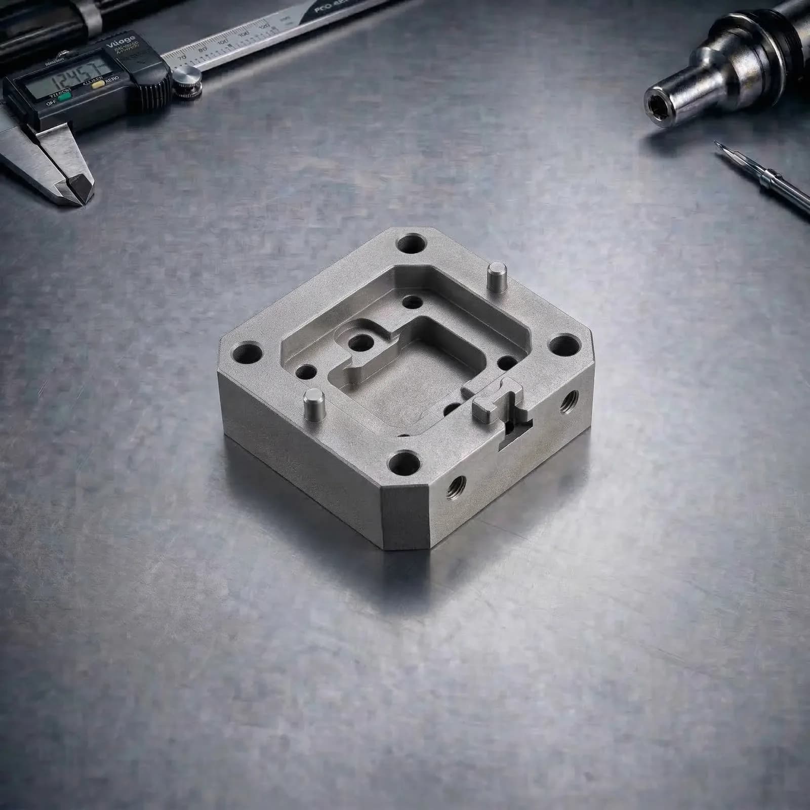
Metal Additive Manufacturing(DMLS / SLM)
Production-grade metal printing for engineered performance. Metal DfAM + support/orientation planning, stress-relief heat treatment, controlled support removal, and machining of CTQ datums—so parts assemble predictably and meet functional requirements.
Precision Focus
Machined CTQ Datums
Typical Lead Time
Days–Weeks
Program Mode
Prototype → Production
Controlled metal Additive Manufacturing workflow
DfAM + orientation/support planning + heat treatment + support removal + machining + CTQ verification.
Metal Additive Manufacturing (DMLS / SLM) Services
Why Choose PREMSA for Metal Additive Manufacturing
PREMSA supports DMLS/SLM metal additive manufacturing when you need high-strength alloys, complex geometry, and production-grade repeatability. We start by defining CTQs (datums, sealing faces, bores, interfaces, fits) and then plan orientation + supports so distortion risk and critical surfaces are controlled.
Metal Additive Manufacturing outcomes are driven by residual stress, support interaction, and post-processing. We align the program around stress-relief heat treatment, controlled separation/support removal, and secondary machining for interfaces that must assemble reliably.
For prototypes, we move fast with fit-focused machining where needed. For production programs, we lock process controls, finish class, heat treat, and inspection plans—delivering metal parts that repeat across lots instead of drifting with geometry and post-processing variables.
What is DMLS / SLM?
DMLS/SLM are metal powder-bed fusion processes that build parts by selectively melting metal powder with a laser layer-by-layer. Parts are created on a build plate, often with supports required to manage overhangs, heat flow, and distortion.
A successful program depends on orientation/support strategy, residual-stress control, heat treatment, support removal access, and machining of CTQ interfaces. These controls determine whether parts are simply “printed” or truly production-ready.
The Metal Additive Manufacturing Workflow
A DfAM-first workflow that controls supports, distortion, heat treatment, and CTQ outcomes.
1. File Intake & Requirements Definition
We review CAD + drawings and confirm CTQs, target quantities, surface/finish requirements, heat treat requirements, and machining expectations.
2. Metal DfAM Review (Supports + Distortion + Machining Plan)
We evaluate overhangs, support access/removal, thin-wall risk, residual stress/distortion drivers, and define which interfaces must be machined for fit.
3. Alloy Selection + Program Plan
We align alloy choice (316L, 17-4PH, Ti-6Al-4V, AlSi10Mg, Inconel 718, etc.) to loads, corrosion/temperature environment, and post-processing needs.
4. Build Planning (Orientation + Supports + Plate Strategy)
We set orientation and supports to protect CTQ faces, manage heat flow, and ensure practical removal and finishing access.
5. Printing & In-Process Monitoring
Parts are built under controlled parameters aligned to density and repeatability targets.
6. Heat Treatment (Stress Relief Standard)
Stress relief is used to stabilize parts prior to aggressive support removal/machining; additional heat treat or HIP is program-dependent.
7. Separation + Support Removal
Parts are separated from the plate (EDM/bandsaw as required) and supports are removed with an access-aware plan to protect critical surfaces.
8. Secondary Ops, Finishing & CTQ Verification
Machining of datums/bores/threads, finishing (blast/peen/polish), and inspection against CTQs with documentation per program requirements.
Supports, Distortion & Repeatability Control
Support Strategy That Protects CTQ Faces
We place supports to manage heat flow and distortion while avoiding sensitive datums and sealing/mating surfaces when possible.
Residual Stress & Distortion Planning
Orientation, geometry strategy, and heat-treat sequencing reduce warp risk—especially on long flats, thin webs, and asymmetric parts.
Machining Plan for Assembly Interfaces
We treat CTQ bores, pins, threads, and sealing lands as post-processed features when repeatability matters.
Practical Removal Access by Design
Support removal and finishing access must be designed in—tight cavities and shielded surfaces can drive cost and risk.
Surface Finish Defined by Function
As-printed metal surfaces are rougher than machined. We align finish class to friction, sealing, fatigue, and cosmetic expectations.
Program Lock for Production Runs
For repeatability, we lock alloy, orientation/support approach, heat treat, secondary ops, and inspection plan across lots.
Technical Advantages
High-Performance Alloys
Print stainless, titanium, aluminum, and nickel alloys for strength, corrosion resistance, and temperature performance.
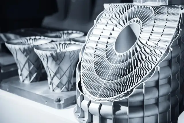
Complex Geometry You Can’t Machine
Internal channels, lattice/lightweighting, conformal paths, and integrated features without multi-piece assemblies.
Fast Iteration Without Tooling
Prototype and pilot builds without casting or forging lead times—then scale with a controlled program.
Production-Ready via Post-Processing
Heat treat + machining of CTQ datums enables predictable fit and functional interfaces.
Surface & Performance Tuning
Blast/peen/polish/coatings as specified to align to wear, sealing, fatigue, and cosmetic requirements.
CTQ Verification for Assemblies
Inspection and documentation scaled to risk: from fit checks to full CTQ reports and evidence packages.
Capacity & Envelope
Part Size & Geometry Range
Feasibility depends on support strategy, distortion risk, and post-processing access. Large flats and thin webs may require ribs, segmentation, or alternate orientation.
Reviewed by CTQ
Tolerances & Machined Interfaces
Tight fits and sealing/mating faces typically require machining. We plan print + stock allowances to machine critical features predictably.
Machined CTQs
Throughput & Program Maturity
Throughput is driven by geometry, support volume, alloy, and post-processing. Stable production programs lock orientation/supports, heat treat, and inspection plans.
Prototype → Production
Not sure if metal Additive Manufacturing is the right fit?
Send CAD + requirements and request a metal DfAM + post-processing plan. We’ll align alloy choice, support strategy, heat treat, machining needs, CTQs, and inspection before you commit.
Quality & Process Control
Metal Additive Manufacturing quality depends on controlling orientation/supports, residual stress, heat treatment, and the post-processing plan for CTQ interfaces. Defining CTQs, datum strategy, fit/sealing faces, required heat treat/HIP, finish class, and quantity targets up front enables repeatable outcomes and stable production programs.
| Category | Technical Capability | Engineering Notes |
|---|---|---|
| CTQs, Datums, Metrology & Capability Targets | Programs are structured around CTQs that drive assembly: datum faces, bore location/size, sealing/mating faces, and interface fits. Capability depends on geometry, alloy, and whether CTQ surfaces are machined. | If a face is a functional datum, plan it as a machined interface (or define acceptable print-only limits explicitly). |
| Density, Porosity Risk & Process Stability | Powder-bed fusion can achieve high density, but porosity and lack-of-fusion risks are geometry and process dependent. Program controls and post-processing selection (including HIP when required) reduce risk for critical applications. | For fatigue-critical or pressure-retaining features, define verification approach (e.g., CTQ testing, CT scan, HIP requirement, coupons as specified). |
| Heat Treatment: Stress Relief, Solution/Age & HIP (as required) | Stress relief is commonly used to stabilize parts before support removal/machining. Some alloys require solution/age heat treatment to reach target properties; HIP may be specified for density/fatigue performance. | Specify required condition (e.g., 17-4PH H900/H1025, solution/aged states, Ti stress-relieved, In718 heat treated/HIP as required by spec). |
| Surface Finish: As-Printed vs. Machined CTQ Interfaces | As-printed metal surfaces are rougher than machined surfaces. Functional sealing/mating faces, precision bores, and threaded interfaces typically require machining or finishing. | Call out finish class for each interface. For sealing and bearing fits, plan machining and appropriate verification. |
Materials
Material selection drives strength, thermal resistance, chemical compatibility, surface quality, dimensional stability, and long-term performance. Share your environment, loads, tolerances, and critical features so we can recommend the right additive process and material family.
Metal Additive Materials (DMLS / SLM)
Metal additive manufacturing supports complex geometries and internal channels. Secondary heat treatment and finish machining are often required.
Post-Processing & Secondary Operations
Additive parts require controlled post-processing to achieve cosmetic grade, interface accuracy, and mechanical performance. Workflows are selected based on geometry, material, and end-use requirements.
Secondary Operations & Surface Options
Metal DfAM Guidelines (DFAM)
Metal Additive Manufacturing is won or lost on supports, residual stress, and post-processing access. These DfAM rules reduce distortion risk, protect CTQ faces, and improve repeatability across builds.
| Design Feature | Recommendation |
|---|---|
| Wall Thickness, Lattices & Supportability | Avoid extreme thin walls without a support plan. Use ribs/fillets to add stiffness and reduce distortion; lattices should be designed with practical powder removal and finishing expectations. |
| Overhangs, Supports & Removal Access | Overhangs require supports. Design for tool access to remove supports and avoid placing supports on critical sealing/mating faces when possible. |
| Orientation, Distortion Control & CTQ Faces | Orient to protect datum faces and critical interfaces. Long flats, thin webs, and asymmetric parts are distortion-prone—use geometry strategy and orientation to minimize warp and protect CTQs. |
| Holes, Threads & Machining Strategy | Treat CTQ holes/bores as post-machined features when alignment matters. Printed threads are typically not ideal for clamp loads—plan tapping/thread-milling or inserts when needed. |
| Tolerances, Datums & Machined Interfaces | Define datums and which surfaces are functional. Use stock allowances for machining critical faces and bores; avoid forcing print-only tolerances onto assembly-critical features. |
| Drawing & Specification Checklist (DMLS/SLM) | Define CTQs, datums, sealing/mating faces + fits, alloy preference (316L/17-4PH/Ti-6Al-4V/AlSi10Mg/In718), required heat treatment/HIP, finish class (as-printed/blast/peen/machined), target quantity, environment exposure, and any needs for machining, inspection evidence, or traceability. |
Applications & Industries
Metal Additive Manufacturing Applications
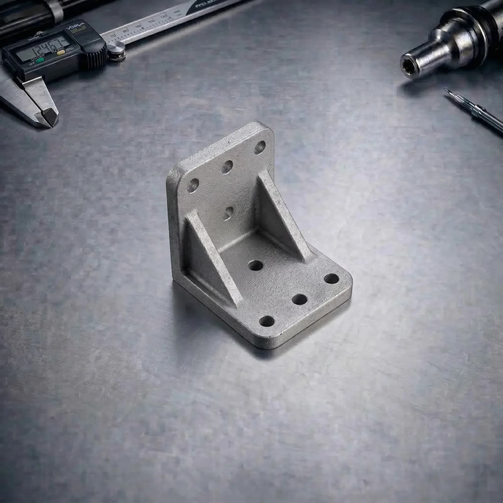
Engineered Brackets & Structural Parts
Lightweighted or integrated brackets where strength-to-weight and geometry integration matter—often with machined datums for assembly.
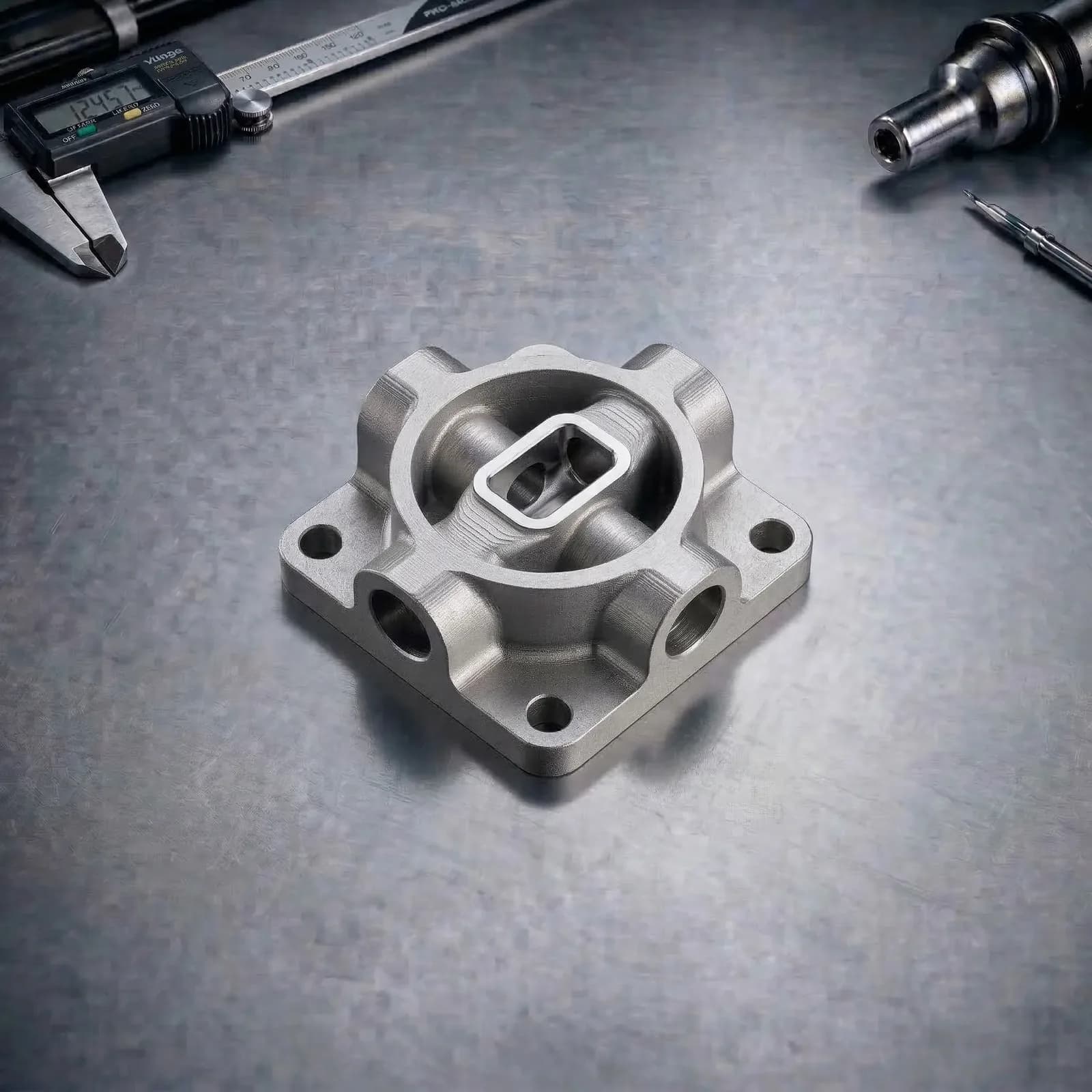
Thermal / Flow Components
Complex internal channels and manifolds where traditional machining is difficult—finishing and verification planned around functional interfaces.
Production Fixtures & Tooling Components
Functional fixtures, nests, and tooling parts in stainless or maraging programs—built fast with post-machining for alignment.
Metal Additive Manufacturing Industries
Aerospace and Defense
Lightweight structural components, complex geometries, and high-performance metal parts optimized for aerospace and defense systems.
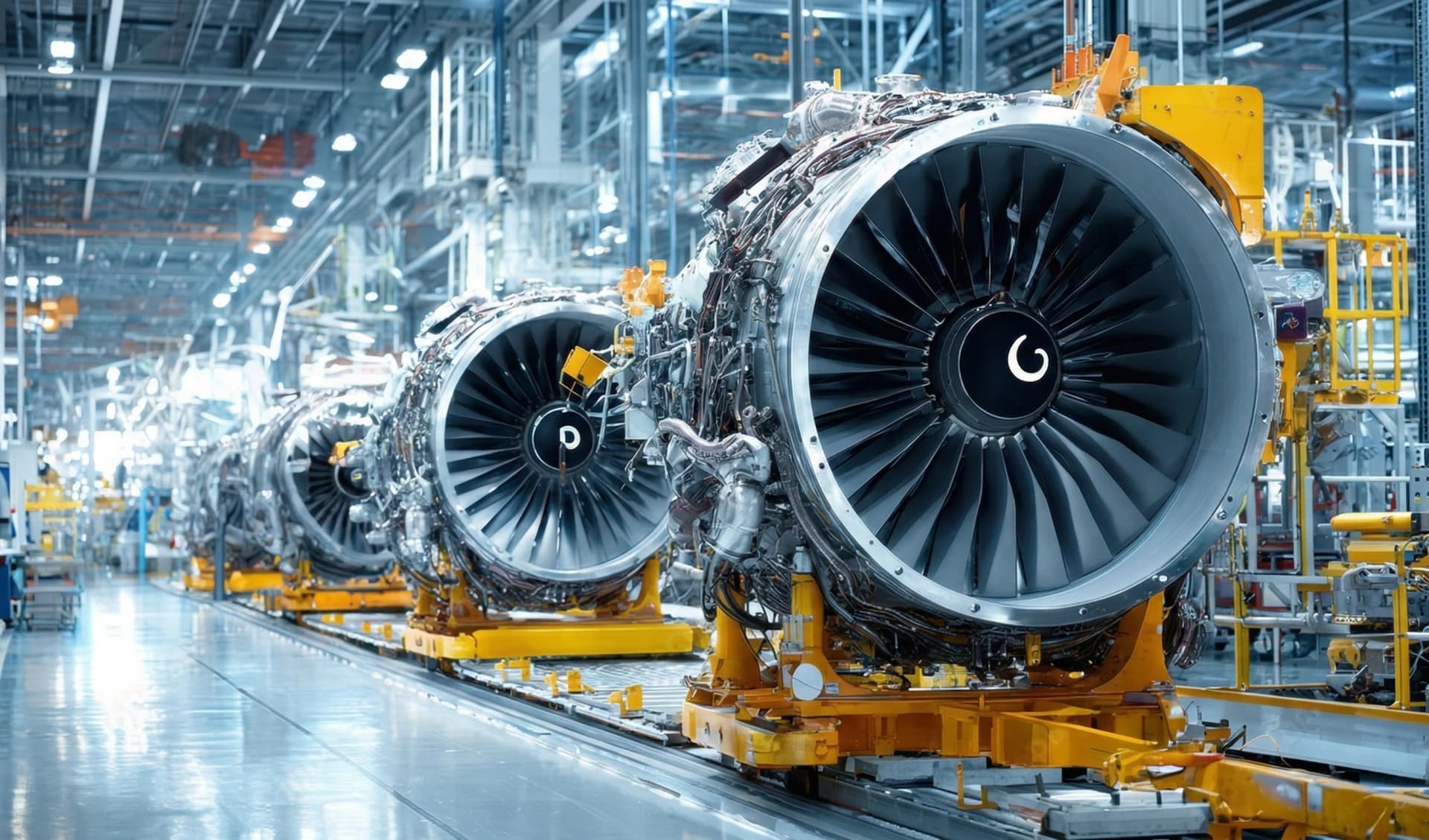
Energy
High-performance metal components for energy systems, including turbine parts, flow components, and thermal management applications.

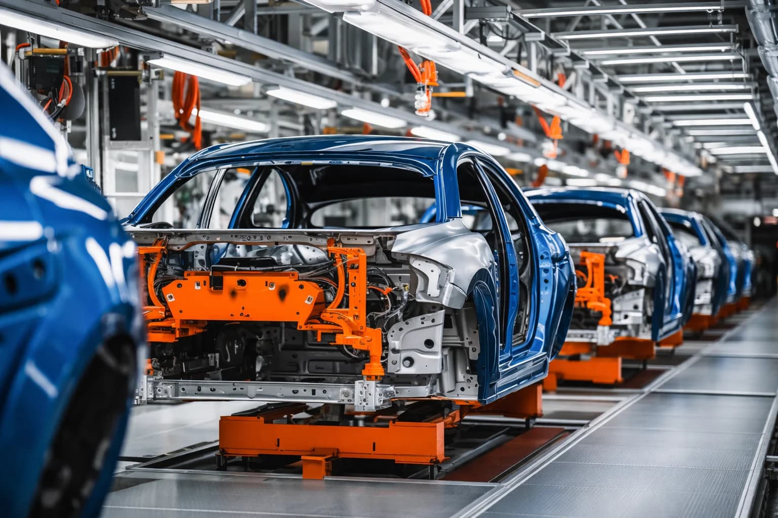
Automotive
Lightweight performance components, rapid prototyping, and complex metal parts for automotive engineering and motorsport applications.
FAQs & Knowledge Base
Metal Additive Manufacturing FAQs
Metal Dmls And Slm
— FDM, SLA/DLP, SLS, MJF, and metal DMLS/SLM — and cross-reference CNC machining when you need post-machined tolerances.
Request a quote when you have 3D files, material, and finish defined.
PREMSA ecosystem
Services, guides, and tools for metal DMLS and SLM
We operate from Monterrey for engineering teams across Mexico and North America. We deliver laser powder-bed metal additive with ISO 2768 tolerances, engineering materials, and prototype-to-production routes. Use the technical references below and quote online with STEP or STL files.
Additive technologies
Engineering tools
- Interactive chart
ISO 2768 Tolerance Chart
General linear and geometric tolerances for machined and formed features.
View chart - Calculator
Tap Drill Size Calculator
Hole diameters for metric, UNC, UNF, and NPT threads.
Open tool - Reference chart
Drill Bit Size Chart
Number, letter, and fractional drill diameters.
View chart
- What should I upload for a DMLS/SLM quote?
- Upload 3D CAD (STEP preferred) and drawings defining CTQs (datums, fits, sealing/mating faces, hole/bores), target alloy, required heat treat/HIP (if any), finish class (as-printed/blast/peen/machined), quantity targets, and any documentation needs (CTQ reports, traceability, inspection evidence).
- Do metal printed parts require supports?
- Usually yes. Supports manage overhangs, heat flow, and distortion. The support strategy also impacts surface condition and post-processing access—so it’s planned during metal DfAM.
- Do you heat treat metal Additive Manufacturing parts?
- Yes—stress relief is commonly used to stabilize parts before support removal and machining. Additional heat treatment (solution/age) or HIP can be included when required by alloy condition, fatigue/density needs, or customer specifications.
- Can you hit tight fits and precision bores with metal AM?
- For assembly-critical fits, we typically machine CTQ interfaces (datums, bores, sealing faces) after printing and heat treatment. This delivers more repeatable results than relying on print-only tolerances for precision interfaces.
- What post-processing options do you support?
- Common programs include stress relief, plate separation (EDM/bandsaw as required), support removal/cleanup, CNC machining of CTQ datums/bores/threads, bead blast/shot peen, and spec-dependent finishing (passivation/electropolish for stainless, coatings/anodize for aluminum when specified).
- What drives cost in DMLS/SLM metal printing?
- Key drivers include part volume, alloy selection, support volume and removal difficulty, heat treatment/HIP requirements, secondary machining for CTQs, surface finishing, and inspection/documentation scope.
Ready for your next project with PREMSA?
Upload your STEP file, set material and quantity, and get DFM review with clear lead times and an online quote.