
3D printing has moved from a lab tool to a practical way to make real parts: brackets, housings, assembly fixtures, spare parts that are no longer available and prototypes that get tested on the machine before anyone pays for a mold or a machined batch.
This guide explains what it is, how it works, which technologies exist, which materials are used and what tolerance you can expect. It also covers what most beginner guides leave out: when a printed part can handle the job and when it is better to machine it.
- What it is and how it differs from subtractive manufacturing
- How it works, from the 3D file to the finished part
- Technologies: FDM, SLA, SLS, MJF and metal
- Materials, tolerances and cost for functional parts
- 3D printing or CNC machining: how to decide
What is 3D printing?
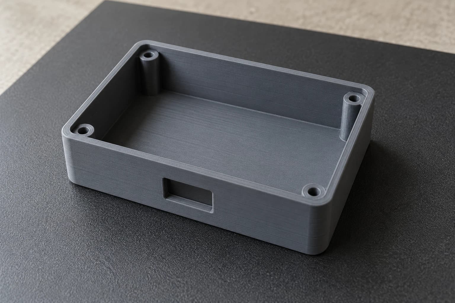
3D printing, also called additive manufacturing, is a process that builds a solid part by adding material in thin layers, one on top of another, following a 3D model. Each layer is a horizontal slice of the part; stacking hundreds or thousands of them produces the complete shape.
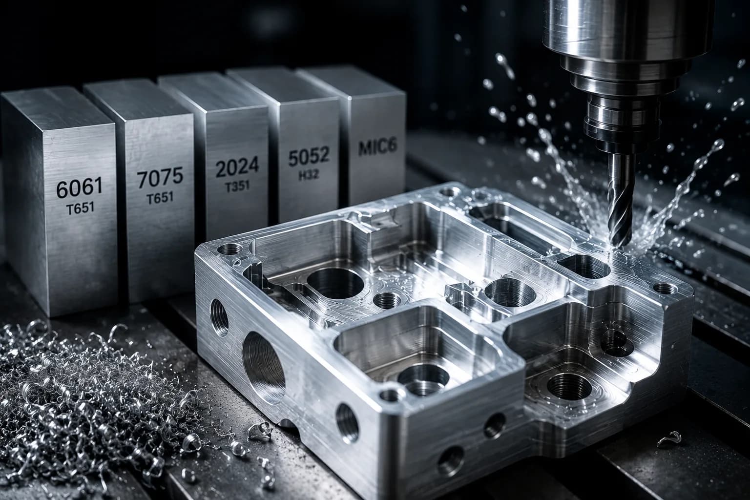
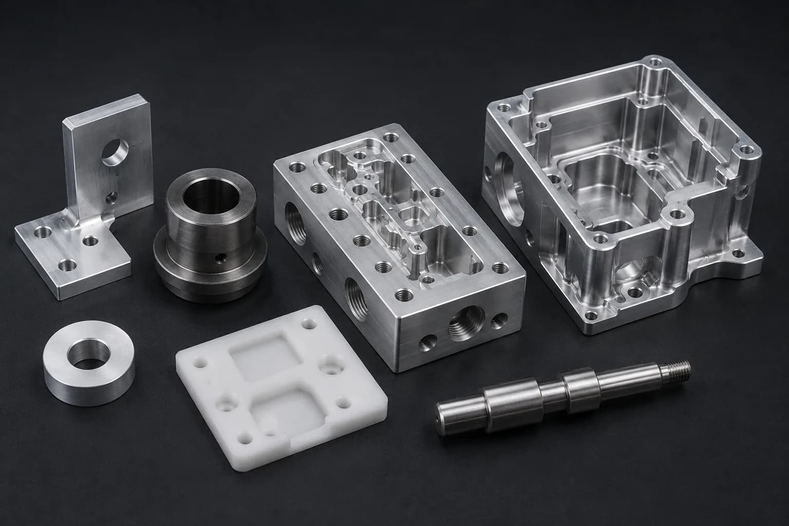
It is the opposite of CNC machining, which starts from a block or a bar and removes material with cutting tools until only the part is left. That is why machining is called subtractive manufacturing: the leftover material becomes chips. In 3D printing, the only material used is the part itself and its supports.
That difference explains most of its strengths and its limits. Since no tool has to reach every surface, 3D printing can make internal channels, lattices and organic shapes that would be expensive or impossible to machine. And since the part is built in layers, the bond between one layer and the next is its weakest point, which does not happen with a part machined from solid bar.
If a part can be described as a shape that grows up from its base, layer by layer, it can almost certainly be printed. The real question is not whether it can be printed, but whether the printed part will hold up to the job.
How 3D printing works: from file to part
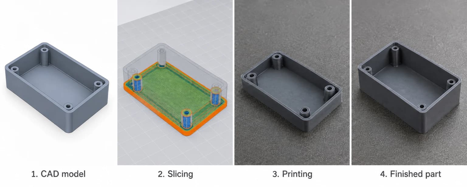
Regardless of the technology, every printed part goes through the same four stages. Understanding them helps you design better and know what to ask for when you get a quote.
1. The 3D model
Everything starts with a digital model of the part. For printing, the most common formats are STL and 3MF, which describe the surface as a mesh of triangles. A STEP file also works and keeps the exact geometry, which is why we recommend it when the part was designed in CAD software such as SolidWorks, Fusion or Onshape.
What matters is that the model is a closed solid: no gaps in the surface, no loose faces and dimensions in the right unit. A file exported in inches when it was designed in millimeters produces a part 25.4 times larger or smaller.
2. Slicing
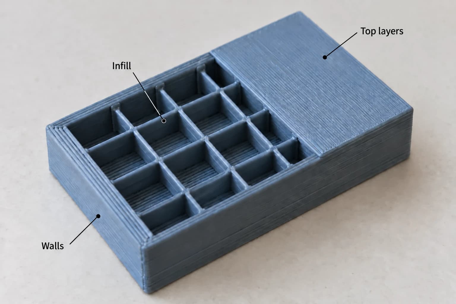
In FDM, the most common technology, a program called a slicer cuts the model into horizontal layers before printing and calculates the machine's path on each one. This is where the settings that most affect strength, finish and print time are defined:
- Layer height: usually between 0.1 and 0.3 mm. A thinner layer gives a better finish but takes longer.
- Walls: the number of perimeters that form the outside of the part. More walls mean more strength.
- Infill: the inside is rarely solid; it is filled with a grid or pattern by percentage, typically 15 to 40%.
- Top and bottom layers: solid layers that close the part at the top and bottom.
- Supports: temporary structures that hold up the areas that would otherwise be printed in mid-air.
- Orientation: how the part sits on the bed. It changes strength, finish and the amount of support.
3. Printing layer by layer
The machine builds the first layer on a bed or platform, moves up or down a fraction of a millimeter and builds the next one. In FDM a hot nozzle lays down melted plastic; in SLA a light source cures liquid resin; in SLS and MJF powder is fused with heat. The principle is the same: one layer at a time.
Print time depends mostly on the size and height of the part. A small part can be done in under an hour; a large housing with high infill can take a full day.
4. Support removal and finishing
When the print is done, supports are removed and the part is cleaned. For many functional applications the part is ready as is. If a better appearance or a tighter dimension is needed at a specific spot, it can be sanded, painted, or have a surface or hole machined after printing.
Types of 3D printing
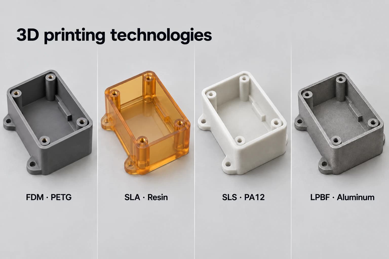
There are several technologies, and each uses a different material and principle. These are the ones used to make parts, not just display models:
| Technology | How it works | Materials | Best for |
|---|---|---|---|
| FDM (fused deposition modeling) | A nozzle melts a thermoplastic filament and lays it down in layers | PLA, PETG, ABS, ASA, TPU, nylon and fiber-filled composites | Functional parts, fixtures, housings and prototypes |
| SLA / DLP (stereolithography) | Ultraviolet light cures liquid resin layer by layer | Photopolymer resins | Parts with fine detail and a smooth surface |
| SLS (selective laser sintering) | A laser fuses plastic powder; the unfused powder acts as support | Nylon PA11 and PA12 | Strong parts with complex geometry, no supports |
| MJF (Multi Jet Fusion) | A fusing agent and heat fuse nylon powder layer by layer | Nylon PA12 | Medium runs of nylon parts |
| Metal (DMLS / SLM) | A laser melts metal powder | Stainless steel, aluminum, titanium | Complex metal parts in specialized industries |
Each technology leaves a different surface and strength. SLA gives the best detail, but resins tend to be more brittle and sensitive to sunlight. SLS and MJF produce very tough nylon parts with no supports and a slightly porous finish. Metal printing solves geometry that cannot be machined, but it costs far more than machining the same part when the geometry allows it.
FDM 3D printing: the most used for functional parts
FDM 3D printing is the most widely used technology for plastic parts that have to work. The reason is practical: the materials are real engineering thermoplastics (PETG, ABS, ASA, nylon), FDM thermoplastics, especially ASA, handle sun and heat better than many SLA resins, and the cost per part stays low even at quantity 1.
In FDM the material comes as a filament wound on a spool. The nozzle heats it until it melts and lays it down in lines that form each layer; as it cools, each line bonds to the one next to it and to the layer below.
What an FDM part can handle
A well-designed FDM part handles real mechanical loads: sensor brackets, guides, covers, guards, assembly jigs and low-load gears. Its weak point is the vertical direction. Lines within the same layer are very well bonded, but the bond between layers is weaker, so the part is less strong when pulled in the direction it was built.
That is why orientation matters as much as material. A hook printed lying flat holds considerably more than the same hook printed standing up, because in the first position the load runs along the lines instead of pulling them apart.
In an FDM part, strength is not the same in every direction. Orienting it well on the bed is often worth more than switching to a more expensive material.
Where FDM falls short
- Tight tolerances: for bearing fits or precision holes, it is better to machine after printing, or to machine the whole part.
- High temperature: PLA softens around 55 °C; for hot environments use ABS, ASA, nylon or polycarbonate.
- Surface: layer lines are visible and can be felt. If the part is cosmetic, it gets sanded or painted.
- Very fine detail: text or walls thinner than 0.8 mm do not print well with a standard 0.4 mm nozzle.
3D printing materials
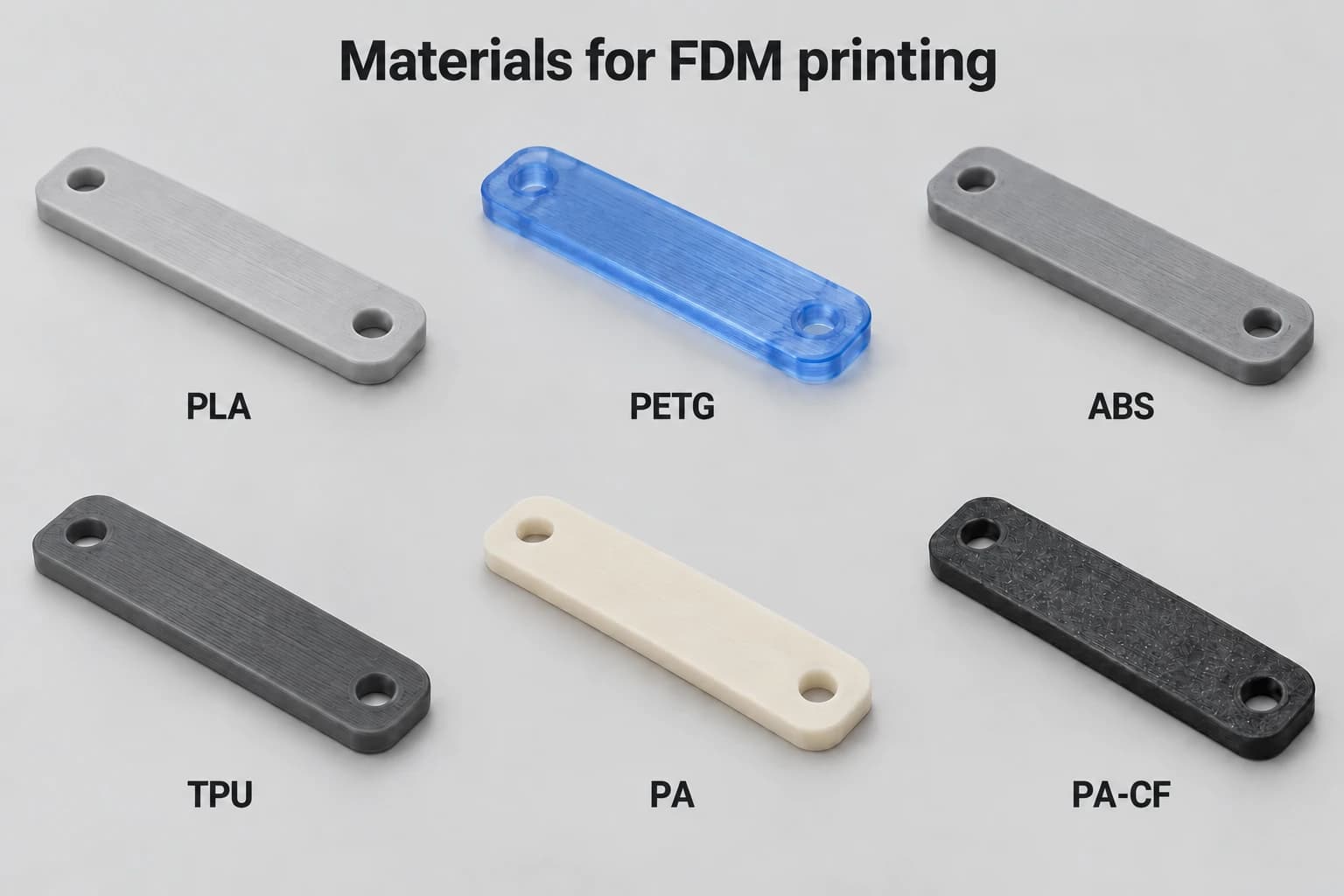
The material decides the strength, the temperature the part can take and how flexible it is. These are the most common FDM materials for functional parts:
| Material | Strengths | Watch out for | Typical uses |
|---|---|---|---|
| PLA | Easy to print, good detail, stiff | Softens around 55 °C | Form prototypes, models, office fixtures |
| PETG | Tough, resists water and mild chemicals | Slightly less stiff than PLA | General functional parts, covers, brackets |
| ABS | Impact and moderate heat resistance | Tends to warp on large parts | Housings, interior automotive parts |
| ASA | Like ABS, but resists sun and weather | Same warping care as ABS | Outdoor parts, covers, signage |
| TPU | Flexible like rubber | Lower dimensional accuracy | Gaskets, bumpers, protectors, seals |
| Nylon and carbon fiber filled | Very resistant to wear and load | Absorbs moisture; needs drying | Gears, bushings, tooling, load brackets |
If you are not sure which one to pick, PETG is a good starting point for functional parts. Move to ASA if the part will sit in the sun, to ABS or nylon if it will run hot or see wear, and to TPU if it has to flex.
FDM tolerances and finish
In FDM, a typical tolerance is around ±0.2 mm on small parts or ±0.2% of the dimension on large parts, whichever is greater, with the right material and geometry; large or thin parts in ABS or nylon may fall outside it. That is enough for most parts that get bolted, assembled with clearance or serve as a support.
Horizontal dimensions are usually more accurate than vertical ones, and holes tend to come out slightly smaller than the model because the plastic shrinks as it cools. If a hole has to take a screw or a pin with a fit, leave clearance in the design or ream it after printing.
- Finish: layer lines are visible; at 0.1 mm layers they can barely be felt, at 0.3 mm they can.
- Downward faces: surfaces that rest on supports come out rougher than the rest.
- Warping: large, flat ABS or nylon parts can curl if they are not designed carefully.
Advantages and limits of 3D printing
Advantages
- No tooling or molds: you can make a single part without investing in a mold; the price per part depends on material, geometry and quantity.
- Free geometry: internal channels, lattices, organic shapes and parts that would need several setups to machine.
- Speed: a part can be ready one or two days after the file is approved.
- Cheap changes: changing the design means changing the file, not rebuilding a mold.
- Little waste: only the material of the part and its supports is used.
Limits
- Weaker between layers than a machined or molded part in the same material.
- Looser tolerances than CNC machining.
- Layer lines on the surface that may need finishing.
- It does not scale like a mold: the price drops as you order more, but for thousands of identical parts injection molding ends up cheaper.
- Fewer materials than the metals and plastics that can be machined.
Industrial applications of 3D printing
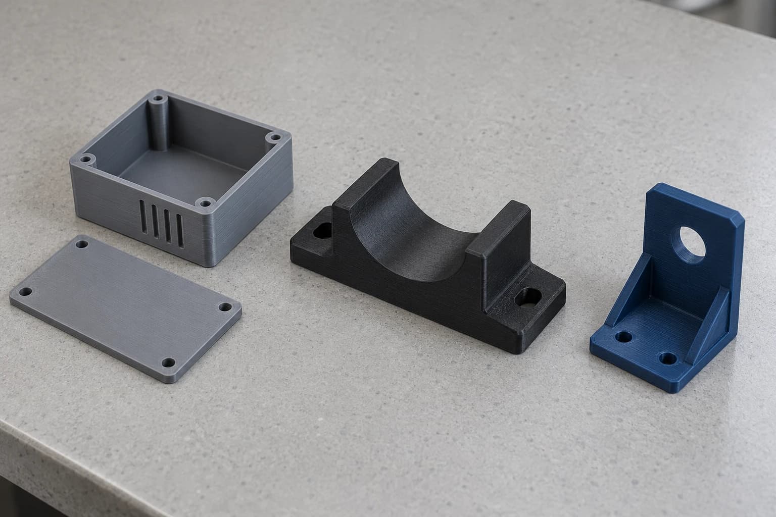
3D printing pays off most on parts that are needed quickly, in small quantities or with a shape that complicates machining:
- Functional prototypes: test fit, assembly and function before machining or building a mold.
- Fixtures, jigs and tooling: assembly guides, drilling templates, inspection holders and guards made to fit each part.
- Spare parts: plastic parts that are no longer made or take weeks to arrive.
- Short production runs: housings, covers and brackets in tens or hundreds, with no mold to pay for.
- Custom parts: variants of the same part for different models or customers.
Real case: a gear for a portal axle gearbox
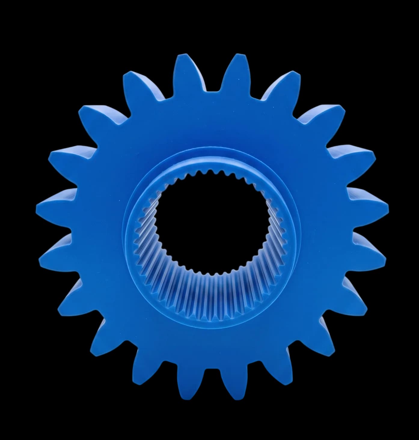
A customer who develops portal axles for off-road vehicles needed to validate a gear from the reduction box that sits at each wheel hub. On a portal axle, that box lifts the axle above the center of the wheel and carries all of the engine's torque to the wheel, so the final gear is made of steel.
Before paying to machine and heat treat the gears, they needed to check three things: that the internal spline fit the shaft, that the teeth meshed properly with their mating gear and that everything fit inside the housing.
Why it was printed in PETG
The test gear was printed in PETG because it is stiff, dimensionally stable and cheap to reprint if something needs correcting. It did not have to carry the vehicle's load, only reproduce the geometry so the box could be assembled and turned by hand. That made it possible to try several versions in days, without spending on steel or heat treatment.
What limitations it had
- It is not a working gear: a printed part cannot take the torque of a portal axle. It validates fit and form, not road use.
- The internal spline needed compensation: plastic shrinks as it cools, so it was opened slightly in the model so the test part would fit the way the machined part would.
- Orientation mattered: it was printed lying flat, with the layers perpendicular to the axis, so the teeth would not break while the box was assembled and taken apart several times.
With the geometry validated, the gear moved to CNC machining in steel, with confidence that it would fit and mesh the first time. This is the most cost-effective use of 3D printing for mechanical parts: make your mistakes in plastic, which is cheap and fast, before you build in metal.
What drives the cost of a 3D printed part
The price of a printed part depends mostly on how much material it uses and how long it keeps the machine busy. The factors that move it most are:
- Size and volume: more material and more layers mean more time.
- Height: a tall part has more layers than a flat one of the same volume.
- Infill and walls: a more solid part is stronger, but uses more material and time.
- Layer height: thinner layers improve the finish and lengthen the print.
- Supports: large overhangs need more support and more work to remove it.
- Material: engineering filaments, such as carbon fiber nylon, cost more than PLA or PETG.
- Quantity: ordering more parts lowers the price of each one.
For examples and how price changes with quantity, see how much 3D printing costs.
3D printing or CNC machining: when to use each
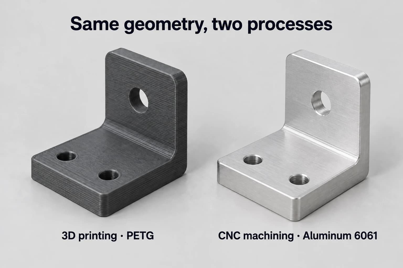
The two complement each other. The decision almost always comes down to three questions: what material the part needs, what tolerance it has to hold and how many parts you will need.
| If your part... | Choose |
|---|---|
| Is plastic, low quantity and geometrically complex | 3D printing |
| Is a prototype to test form and fit | 3D printing |
| Needs metal (aluminum, steel, stainless, brass) | CNC machining |
| Has tolerances of ±0.05 mm or tighter | CNC machining |
| Must be equally strong in every direction or carry high loads | CNC machining |
| Is an engineering plastic such as acetal or PEEK in block form | CNC machining |
| Is a custom fixture or tool for the line | 3D printing, or CNC if it sees heavy wear |
A common path is to start with a printed part to validate the design and, once approved, move it to CNC machining for production or for the metal version. In the same quote you can switch between the two processes and compare prices.
How to prepare your file to quote 3D printing
- Export an STL, 3MF or STEP of the complete solid, in millimeters.
- Check that it is a closed solid, with no gaps or loose faces.
- Avoid walls thinner than 0.8 mm and details smaller than the nozzle.
- State the material, or what the part has to do if you are not sure which one to choose.
- Note in the comments if a hole or dimension is critical, or if the part has an important load direction.
Frequently asked questions about 3D printing
Straight answers on strength, tolerances, materials and when printing a part makes sense.
- How strong is a 3D printed part?
- It depends on the material, the infill and the orientation. An FDM part in PETG, ABS or nylon with enough walls handles real functional loads, such as brackets, covers and jigs. Its weak point is the bond between layers, so it is less strong when the load pulls the layers apart.
- What tolerance does FDM 3D printing hold?
- A typical tolerance is ±0.2 mm on small parts or ±0.2% of the dimension on large parts, with the right material and geometry. If you need something tighter on a hole or a face, it can be machined after printing, or the whole part can be made with CNC.
- What file do I need to print a part?
- An STL, 3MF or STEP of the complete solid, in millimeters. STEP keeps the exact geometry and is the best option if you designed the part in CAD software.
- How long does it take to print a part?
- A small part can print in under an hour and a large one can take a day. The full lead time appears in your quote when you upload the file.
- Is 3D printing good for production?
- Yes, for short runs of tens or hundreds of parts, especially when the geometry is complex or the design changes often. For thousands of identical parts, injection molding is usually cheaper.
- Which material should I choose for my part?
- PETG is a good starting point for functional parts. Use ASA if it will sit in the sun, ABS or nylon if it runs hot or sees wear, and TPU if it has to flex.
- Can metal parts be 3D printed?
- Yes, with technologies such as DMLS or SLM, but the cost is high. When the geometry allows it, machining the part in metal is usually cheaper and more accurate.
- When should I machine instead of print?
- When the part needs metal, tolerances of ±0.05 mm or tighter, the same strength in every direction or an engineering plastic such as acetal or PEEK. For prototypes, short runs and complex plastic geometry, printing makes sense.
It depends on the material, the infill and the orientation. An FDM part in PETG, ABS or nylon with enough walls handles real functional loads, such as brackets, covers and jigs. Its weak point is the bond between layers, so it is less strong when the load pulls the layers apart.
A typical tolerance is ±0.2 mm on small parts or ±0.2% of the dimension on large parts, with the right material and geometry. If you need something tighter on a hole or a face, it can be machined after printing, or the whole part can be made with CNC.
An STL, 3MF or STEP of the complete solid, in millimeters. STEP keeps the exact geometry and is the best option if you designed the part in CAD software.
A small part can print in under an hour and a large one can take a day. The full lead time appears in your quote when you upload the file.
Yes, for short runs of tens or hundreds of parts, especially when the geometry is complex or the design changes often. For thousands of identical parts, injection molding is usually cheaper.
PETG is a good starting point for functional parts. Use ASA if it will sit in the sun, ABS or nylon if it runs hot or sees wear, and TPU if it has to flex.
Yes, with technologies such as DMLS or SLM, but the cost is high. When the geometry allows it, machining the part in metal is usually cheaper and more accurate.
When the part needs metal, tolerances of ±0.05 mm or tighter, the same strength in every direction or an engineering plastic such as acetal or PEEK. For prototypes, short runs and complex plastic geometry, printing makes sense.
Related resources
- 3D printing in Monterrey
- FDM 3D printing
- Prototype 3D printing
- What is CNC machining?
- How much does 3D printing cost?

Written by
Adrian Cavazos and the PREMSA Engineering Team
Adrian Cavazos, founder of PREMSA Industries, leads a manufacturing engineering team specialized in CNC machining and 3D printing. The team works closely with customers to optimize designs, improve manufacturability (DFM) and make functional parts from prototypes to production.