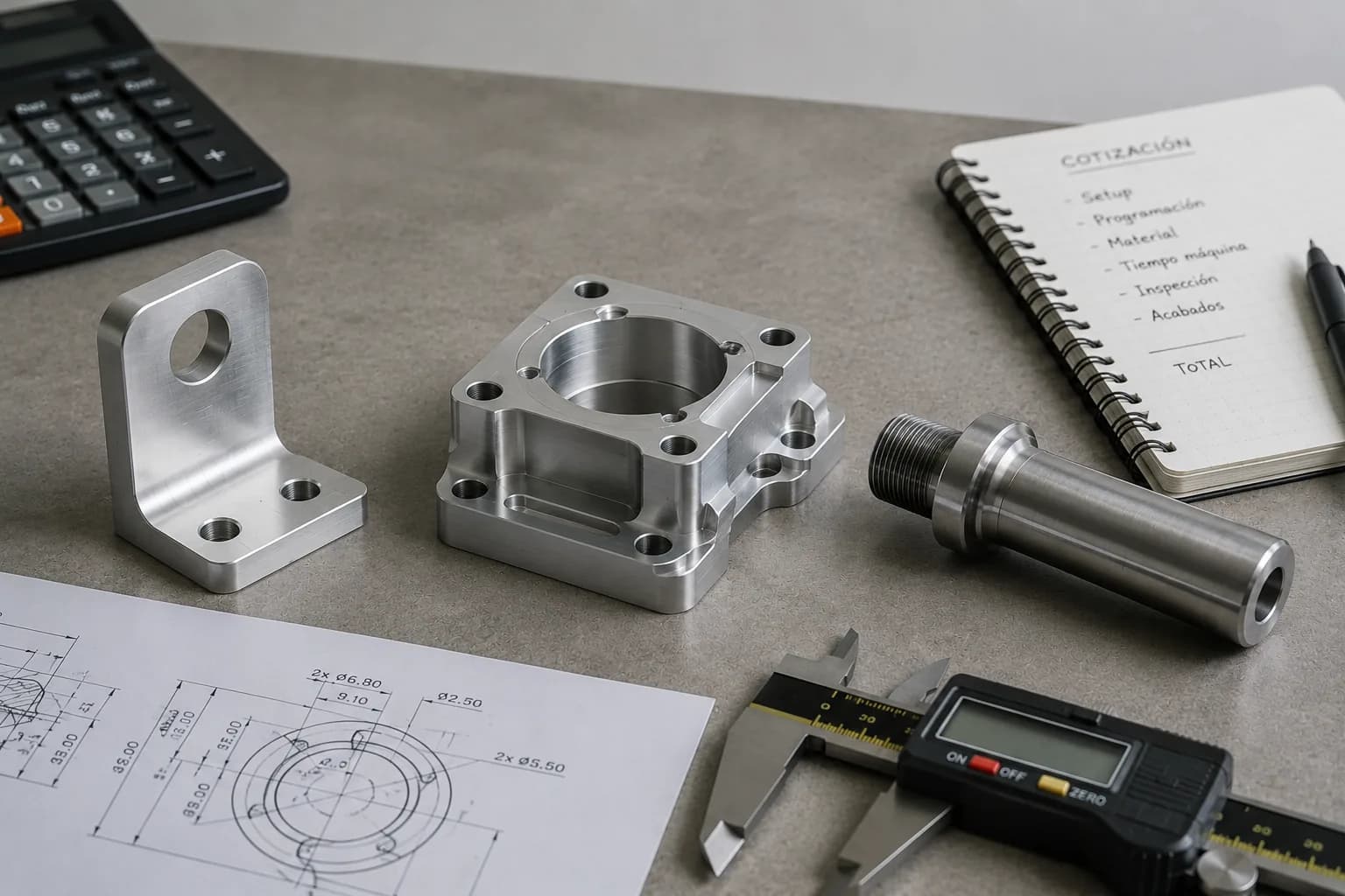
Aluminum is one of the most used materials in CNC machining, but choosing the wrong alloy can increase costs, generate deformations or complicate finishes without providing any real advantage to the part.
Two seemingly similar components can have very different prices. A part made of 6061-T651 with functional tolerances and geometry compatible with standard tools is usually much more economical than one made of 7075-T6 with deep cavities, hard anodizing and close tolerances throughout the part. Although both are made of aluminum, the machine time, manufacturing risk and inspection requirements are completely different.
Therefore, the selection of aluminum should not be based solely on mechanical resistance or availability. Factors such as alloy, temper, geometry, dimensional stability and surface finish have a direct impact on machinability and final cost.
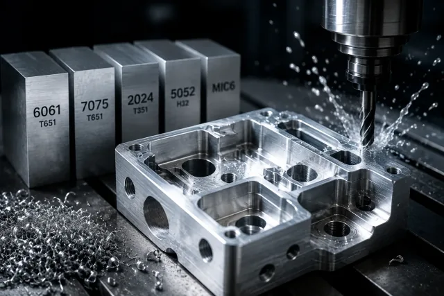
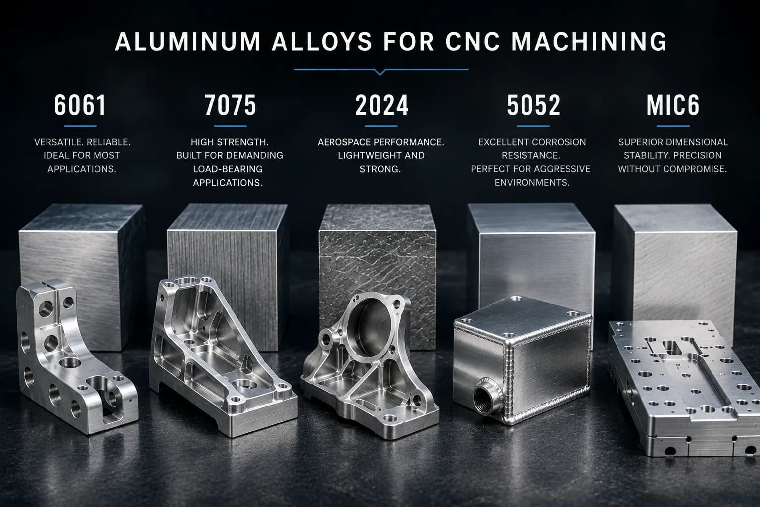
In this guide we explain when to use 6061, 7075, 2024, 5052 or MIC6, how temper influences behavior during machining and what design decisions can reduce risk, production time and cost without compromising part performance.
Why aluminum dominates CNC machining
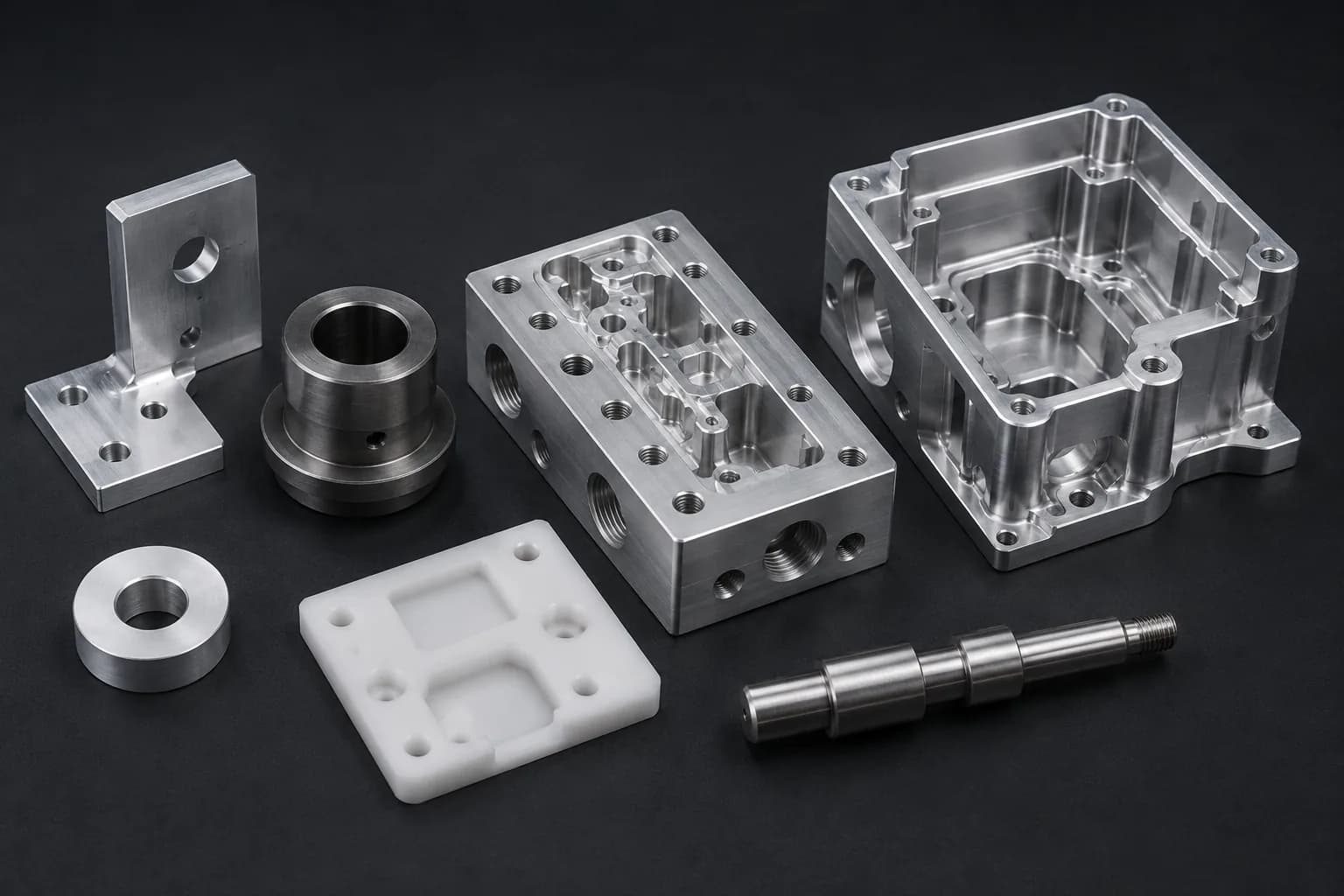
Aluminum has become the go-to material for much of modern CNC manufacturing because it combines properties rarely matched in other materials: low density, high machinability, good dimensional stability, excellent strength-to-weight ratio, and wide industrial availability.
From functional prototypes to repetitive production, aluminum allows large volumes of material to be removed at speeds significantly higher than those used in carbon, stainless or superalloy steels. This translates into shorter cycle times, lower tool wear, lower energy consumption per part, and higher overall process productivity.
In addition to their favorable cutting behavior, many aluminum alloys offer sufficient mechanical strength for structural applications, good corrosion resistance, and compatibility with surface finishes such as anodizing, chromating, painting, and specialized coatings. As a result, aluminum appears recurrently in aerospace components, automation systems, medical devices, industrial electronics, robotics, electric mobility and OEM machinery.
However, assuming that all aluminum behaves the same is one of the most common mistakes in engineering. Seemingly small differences in alloy, temper or form of delivery can affect dimensional stability, surface finish, tool life, response to anodizing and even overall manufacturing cost.
- Low density (~2.70 g/cm³): approximately one third the density of steel, allowing weight to be reduced without sacrificing rigidity in many applications.
- High material removal rates: cutting speeds that can exceed several times those used in conventional steels, significantly reducing machine time.
- Excellent strength-to-weight ratio: Alloys such as 6061-T6 and 7075-T6 offer high structural capacities with a considerably lower mass than ferrous materials.
- High thermal conductivity: Facilitates heat dissipation both during the machining process and in the final application of the part.
- Lower cutting load: generates lower machining forces than many steels, allowing longer tools, greater feeds and less deformation of thin parts.
- Wide compatibility with surface finishes: Type II anodizing, Type III hard anodizing, chrome plating, bead blast and industrial paint.
- Global Industrial Availability: Alloys such as 6061, 7075, 2024, 5052 and MIC6 are widely available in bar, plate, tube and commercial profiles.
- Excellent stability for prototypes and production: Facilitates the transition from a single piece to repetitive batches while maintaining dimensional control and process repeatability.
Aluminum alloys for CNC: when to use and when to avoid
One of the most common questions during a CNC quote is: *what aluminum should I use?* The answer is rarely as simple as choosing the strongest or cheapest alloy. Each family of aluminum was developed to solve different problems and presents different compromises in mechanical strength, dimensional stability, corrosion resistance, machinability, response to anodizing and cost.
In practice, many parts end up over-engineered because a high-performance alloy is selected without a real functional need. In other cases the opposite is true: an economical material is used in applications where loads, fatigue or the environment demand superior properties. The result may be an unnecessary increase in costs or a component that does not meet its expected useful life.
Correct selection begins with understanding which property dominates the application. Is the priority structural resistance? Dimensional stability? Corrosion? Weight? Fatigue? Surface finish? Answering these questions often leads quickly to one or two candidate alloys rather than analyzing the entire available catalog.
Below are the aluminum alloys most used in industrial CNC machining, when they provide real value and when there are usually more appropriate alternatives.
6061-T6/T651 — the industry standard for most CNC parts
Aluminum 6061-T6 is probably the most used alloy in CNC manufacturing. Its popularity comes from an exceptional balance between mechanical strength, corrosion resistance, commercial availability, cost and ease of machining.
For most industrial applications, 6061 offers sufficient structural capacity without the cost overruns associated with higher performance materials. Additionally, it responds well to secondary processes such as anodizing, painting and mechanical assemblies, making it the natural starting point for new designs.
When there is uncertainty about which aluminum to select, 6061-T651 is usually the safest initial reference from a technical and economic point of view.
- Typical Strength: ~290–310 MPa tensile strength.
- Main advantage: excellent balance between performance, availability and cost.
- Machinability: high, with good chip evacuation and consistent surface finish.
- Response to anodizing: very good, especially for cosmetic and functional finishes.
- When to use: brackets, housings, bases, fixtures, manifolds, plates, automation, robotics, industrial electronics and functional prototypes.
- When to Avoid: When the required strength-to-weight ratio clearly justifies materials such as 7075 or when the application is dominated by specific fatigue requirements.
7075-T6 — when resistance is the priority
aluminum 7075-T6 is used when weight and mechanical strength limitations are more important than the cost of the material. With mechanical properties that can approach certain low-alloy steels, 7075 has become a reference for structural components where every gram matters.
Its main advantage is an exceptional strength-to-weight ratio. This allows mass to be reduced without sacrificing load capacity, which is why it frequently appears in aerospace applications, high-performance mobility systems, advanced automation and highly stressed components.
However, the 7075 is not simply a 'stronger 6061'. It also involves higher material cost, lower natural corrosion resistance, and a different response to certain surface processes. Therefore, the decision to migrate from 6061 should be supported by a real structural need and not only by the search for the maximum available resistance.
- Typical Strength: ~510–570 MPa tensile strength.
- Main Advantage: One of the highest strength-to-weight ratios available among commercial aluminum alloys.
- Machinability: good, although generally with higher material costs than 6061.
- Response to anodizing: Acceptable, but less uniform than 6061 due to its chemical composition.
- When to use: lightweight structural components, high load supports, aerospace systems, advanced automation and applications where reducing weight is critical.
- When to avoid: General parts where 6061 serves the purpose, highly corrosive applications without adequate surface protection, or material cost sensitive projects.
2024-T3/T4 — designed to resist fatigue
Aluminum 2024-T3 occupies a particular position within high-performance alloys. Although it is often compared to 7075 for its superior mechanical properties than 6061, its true strength is not only static resistance, but its behavior under repetitive loads.
When a part is subjected to thousands or millions of loading cycles during its useful life, fatigue resistance becomes as important as ultimate strength. In this scenario, 2024 has historically been used in aeronautical structures, mobility components and systems where variable loads dominate the design.
The downside is its lower natural resistance to corrosion due to its relatively high copper content. For this reason, many applications require surface treatments or controlled environments to take advantage of their mechanical advantages without compromising durability.
- Typical Strength: ~430–480 MPa tensile strength.
- Main advantage: excellent performance under cyclic loads and repetitive stresses.
- Machinability: good, with productivity similar to other aeronautical alloys.
- Corrosion response: less than 6061 and generally requires greater attention in aggressive environments.
- When to use: Fatigue components, aeronautical structures, specialized mobility systems and applications with repetitive loading.
- When to avoid: Corrosive environments without surface protection, applications where corrosion resistance is more important than mechanical strength, or designs where 6061 adequately meets the requirements.
5052-H32 — when corrosion matters more than resistance
Aluminum 5052-H32 belongs to a family of alloys developed to offer excellent corrosion resistance and good formability, even in environments where other aluminum alloys can degrade more quickly. Although it is rarely the first choice for machined structural components, it does have an important place in applications exposed to moisture, marine environments, mild chemicals and industrial equipment where environmental durability takes a higher priority than maximum mechanical strength.
Unlike 6061 or 7075, 5052 is especially prized in components made from sheet metal due to its ability to bend, form, and weld without presenting the same risks of cracking or loss of mechanical properties. For this reason it is common to find it in cabinets, covers, panels, enclosures, tanks and metal manufacturing components that subsequently require secondary machining operations.
In applications where corrosion dominates the design, 5052 often offers a more appropriate solution than attempting to protect structural alloys through additional coatings. However, when mechanical loading increases or structural rigidity becomes critical, materials such as 6061 or 7075 typically represent a better alternative.
- Typical Strength: ~220–260 MPa tensile strength.
- Main advantage: excellent natural resistance to corrosion without the need for special treatments.
- Formability: Far superior to most structural aluminum alloys.
- Weldability: excellent for light structures and metal fabrication.
- When to use: Humid environments, marine applications, cabinets, covers, tanks, sheet components and parts with bending operations.
- When to avoid: High-load structural components, parts where the strength-to-weight ratio is critical, or applications where 6061 and 7075 provide significant mechanical advantages.
MIC6 — dimensional stability above strength
MIC6 aluminum was not developed to compete with structural alloys such as 6061 or 7075. Its purpose is different: to provide an extremely stable, flat and stress-free plate for applications where geometric precision is more important than maximum strength.
While a conventional plate can warp after removing large amounts of material due to residual stresses built up during the rolling process, MIC6 is manufactured using specialized casting and stress relief processes specifically designed to minimize this behavior. As a result, it is one of the preferred options for precision tables, fixtures, inspection bases, tooling, jigs and components where flatness must be maintained even after extensive machining operations.
In many tooling projects, the additional cost of using MIC6 is quickly recouped by reducing rework, manual adjustments and warping issues during manufacturing. However, its relatively low mechanical strength means that it should not be considered as a direct replacement for structural alloys where load capacity is a critical requirement.
- Main advantage: Exceptional dimensional stability and minimal post-machining deformation.
- Flatness: significantly higher than most conventional laminated plates.
- Residual stresses: Extremely low thanks to its manufacturing process.
- Machinability: excellent for large volumes of material removal.
- When to use: fixtures, tooling, precision tables, inspection bases, mounting plates and critical reference surfaces.
- When to avoid: structural components subjected to high loads, applications where mechanical strength is the main design criterion or parts where 6061-T651 can adequately fulfill the function.
| Alloy | Typical resistance | Machinability | Corrosion | Dimensional stability | Relative cost | Typical application |
|---|---|---|---|---|---|---|
| 6061-T651 | ~290–310 MPa | Excellent | Very good | Good | $ | Brackets, housings, manifolds, plates, automation and general purpose |
| 7075-T6 | ~510–570 MPa | Very good | Average | Good | $$$ | Lightweight structural components and high load applications |
| 2024-T3/T4 | ~430–480 MPa | Very good | Medium-low | Good | $$$ | Parts subject to fatigue and repetitive cyclic loading |
| 5052-H32 | ~220–260MPa | Good | Excellent | Good | $$ | Foil, cabinets, marine environments and equipment exposed to moisture |
| MIC6 | ~150–180MPa | Excellent | Good | Excellent | $$$ | Fixtures, tooling, precision tables and reference plates |
If there is no specific technical requirement that requires another option, 6061-T651 is usually the best starting point for most CNC parts. When the priority is to maximize structural strength, 7075-T6 typically becomes the next candidate. If the application is dominated by cyclic loading, 2024-T3/T4 can offer significant fatigue benefits. For corrosive environments or components manufactured from sheet metal, 5052-H32 is usually a better choice. When dimensional stability and flatness are critical, especially in fixtures and tooling, MIC6 often justifies its additional cost by reducing deformations and rework.
How to select the correct alloy
The best alloy is not necessarily the strongest or the most expensive. Correct selection depends on identifying which requirement dominates the part design. In most projects, a single property usually has much more impact than the others: structural strength, fatigue, corrosion resistance, dimensional stability or cost.
For that reason, selection should begin by defining the actual function of the component and not by comparing data sheets. Choosing an alloy with properties far superior to those required typically increases cost without generating practical benefits, while selecting an insufficient alloy may compromise performance, service life or reliability.
- For most industrial applications, 6061-T651 remains the most balanced starting point for its combination of strength, machinability, availability and cost.
- When strength-to-weight ratio is the dominant factor and every gram matters, 7075-T6 often justifies its additional cost.
- If the part will be subjected to millions of load cycles during its useful life, 2024-T3/T4 can offer significant advantages in fatigue resistance.
- Where exposure to moisture, marine environments or corrosive agents dominates the design, 5052-H32 is often a more appropriate alternative to conventional structural alloys.
- For fixtures, tooling, precision tables or plates where flatness and dimensional stability are critical, MIC6 typically provides better results than a conventional laminated plate.
- Before releasing any design, always validate the impact of the alloy on machinability, availability, surface finishes and total manufacturing cost.
Aluminum Hardening: Why T651 Can Save an Entire Part
When selecting an aluminum alloy, most people focus solely on the material number: 6061, 7075, 2024 or 5052. However, the temper can be just as important as the alloy itself.
Tempering defines the metallurgical state of the material after heat treatments, mechanical deformation and stabilization processes. These differences directly affect mechanical strength, dimensional stability, behavior during cutting and risk of deformation after machining.
In simple pieces the difference can go unnoticed. However, in components with deep cavities, large material removal volumes, thin walls, or large precision surfaces, selecting the incorrect temper can cause warping, dimensional movement, rework, or even complete part scrapping.
One of the most common mistakes is assuming that two 6061 aluminum plates will behave the same during machining. In fact, a 6061-T651 plate typically maintains its geometry much better after cutting than a plate without adequate internal stress relief. When large amounts of material are removed, these stresses can be released and deform the part even after it has properly exited the machine.
| Temper | Description | Behavior during machining | Main advantages | Typical applications |
|---|---|---|---|---|
| T6 | Solution heat treatment followed by artificial aging | Good balance between resistance and machinability | Wide availability and excellent mechanical properties | General industrial use |
| T651 | T6 with stress relief through controlled stretching | Less tendency to warp during and after machining | Greater dimensional stability and lower risk of warping | Plates, fixtures, deep cavities and critical surfaces |
| EITHER | Fully annealed material | Soft material with greater tendency to burr and adhesion | Excellent formability and bending | Sheet forming and manufacturing processes |
| T4 | Solution Treated and Naturally Aged | Intermediate properties that depend strongly on the alloy | Good compromise between ductility and resistance | Aeronautical and specialized applications |
For most parts machined from plate, T651 is usually the preferred choice when there is a risk of warping. The additional material cost is usually negligible compared to the cost of a finished part that loses flatness, concentricity, or position after releasing internal stresses.
In precision applications, the difference between a stable part and a problematic part is often not in the alloy selected, but in the temper with which the material arrived at the workshop.
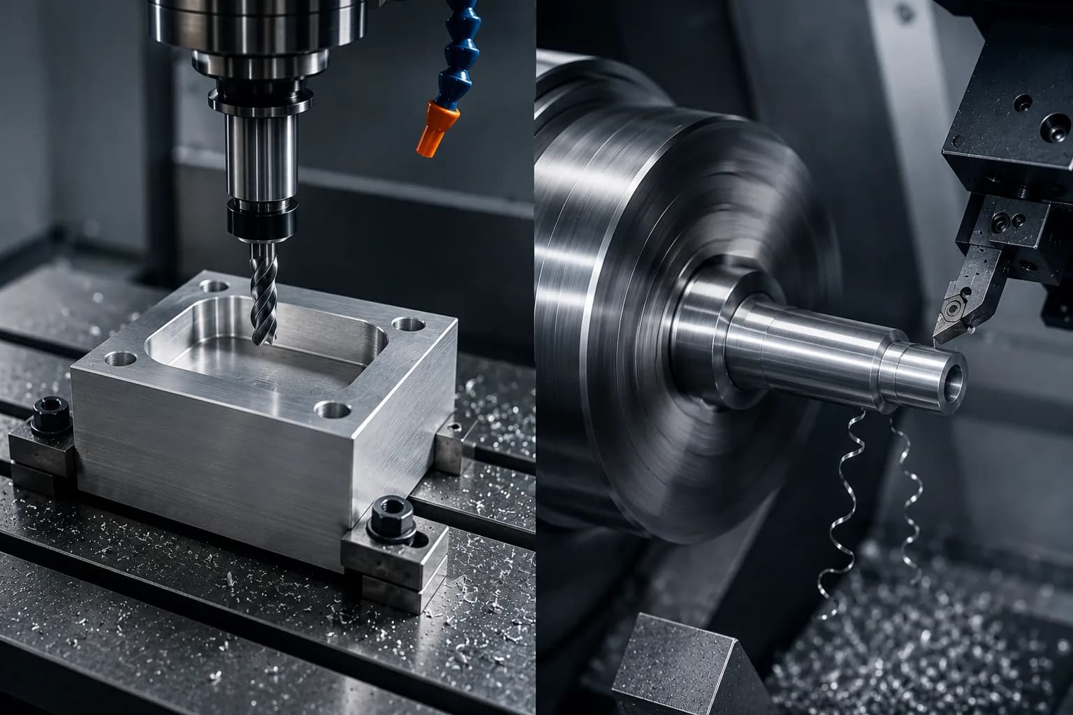
Milling vs turning in aluminum: geometry defines the process
One of the most important advantages of aluminum is that it can be efficiently machined on both machining centers and CNC lathes. However, productivity, precision and final cost depend directly on choosing the correct process for the geometry of the part.
Generally speaking, prismatic parts dominated by flat faces, cavities, pockets, holes and multiple orientations are usually manufactured by CNC milling. In contrast, revolution parts where the main geometry rotates around a central axis are typically produced using CNC turning.
Although this difference seems simple, selecting the wrong process can multiply cycle times, increase setups, require complex fixings or even make a part unfeasible from an economic point of view. For that reason, during the DFM review we usually first analyze what percentage of the geometry is naturally prismatic and what percentage is rotational.
Aluminum favors both processes thanks to its low cutting forces, good chip evacuation and ability to operate at speeds significantly higher than those used in ferrous materials. This allows you to take advantage of high feed strategies, high helix carbide tools and modern machining paths without compromising productivity or surface finish.
| Factor | CNC milling | CNC turning |
|---|---|---|
| Dominant geometry | Prismatic | Rotally or axially symmetric |
| Typical examples | Brackets, housings, manifolds, plates, fixtures | Axles, bushings, pulleys, spacers, adapters |
| Main cost driver | Number of setups, cavities, depth of pockets and tolerances between faces | Cycle time associated with diameter, length and volume removed |
| Main advantage | Great geometric freedom | Very high productivity in revolution parts |
| Common Critical Tolerances | Position, perpendicularity, flatness and parallelism | Concentricity, circularity and runout |
| Common problems | Chatter, tool deflection and thin wall deformation | Burr, vibration on long pieces and concentricity control |
| Production scalability | Medium to high | Very high |
From a cost perspective, one of the most useful rules of thumb is that revolution parts will almost always be cheaper when they can be produced entirely on a CNC lathe. A stepped shaft, bushing, or spacer is typically made much faster on a lathe than on a machining center. Similarly, attempting to manufacture a complex housing or manifold using predominantly turning operations often results in unnecessary cycle times and costs.
In modern designs there are also hybrid parts that combine prismatic and rotational characteristics. In these cases, lathes with live tools and Y axis, multitasking centers or combined machining sequences can intervene. The final decision depends on the geometric complexity, production volume, required tolerances and selected manufacturing strategy.
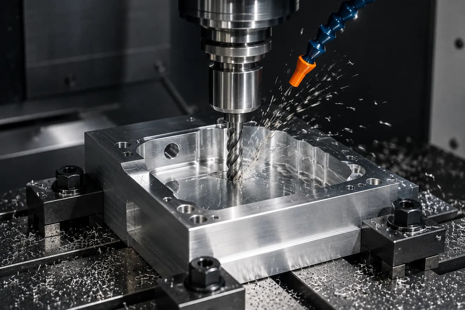
Aluminum cutting parameters: why it can be machined so quickly
One of the reasons aluminum dominates much of modern CNC manufacturing is its ability to withstand material removal rates significantly higher than those used in conventional steels. Its low relative hardness, lower cutting force and excellent thermal conductivity allow working at high surface speeds while maintaining good tool life and consistent surface finishes.
However, productivity does not depend solely on increasing RPM or feed. The ability to efficiently machine aluminum is the result of a balance between tool geometry, chip evacuation, clamping stability, CAM strategy and specific behavior of the alloy used.
In CNC milling operations, aluminum often benefits from tools designed specifically for non-ferrous materials, with large chip clearances, high helix angles, and cutting strategies that maintain a constant load on the cutting edge. This allows you to take advantage of the material's removal capacity without generating heat accumulation or premature deterioration of the tool.
| Factor | General recommendation | Impact on the process |
|---|---|---|
| cutting speed | High compared to steels | Increase productivity and reduce cycle time |
| Number of cutting edges | 2–3 edges in most applications | Improves chip evacuation and reduces the risk of adhesion |
| helix angle | 35°–45° | Reduces cutting forces and improves surface finish |
| Machining strategy | Climb milling and trajectories HEM/trocoidales | Maintains stable load and improves tool life |
| Chip evacuation | Critical priority | Prevents chip trimming and surface defects |
| Refrigeration | Air, MQL or refrigerant depending on application | Reduces adhesion and stabilizes the process |
The two most common problems when machining aluminum
Despite its excellent machinability, aluminum presents two recurring failure modes during machining: BUE (Built-Up Edge) and chatter.
BUE occurs when aluminum particles begin to adhere to the cutting edge, forming an accumulated layer that modifies the effective geometry of the tool. As this buildup grows, the surface finish worsens, dimensions begin to vary, and the risk of tool breakage increases. This phenomenon is usually associated with poor chip evacuation, inadequate tool geometries, or cutting conditions outside the optimal window.
Chatter, on the other hand, is a self-excited vibration that appears when the combined rigidity of machine, tool, fixture and part is insufficient to absorb the dynamic forces generated during cutting. In aluminum it usually manifests itself especially in deep cavities, long tools and thin walls.
In both cases, the solution is rarely simply to reduce RPM. Effective corrections typically involve modifications to the CAM strategy, tool changes, reduction of overhang, improved clamping, or adjustments to radial and axial load distribution. From a manufacturing perspective, many of these situations can be prevented from the design stage through adequate internal radii, better tool access, and thicknesses compatible with the process.
Tolerances in aluminum: what really costs precision
One of the biggest advantages of aluminum is its ability to achieve close tolerances with relative ease compared to many ferrous materials. Its low hardness, stability during cutting and lower machining forces allow excellent dimensional results using modern carbide tools and well-controlled process strategies.
However, reaching a specific tolerance and maintaining it repetitively are not exactly the same problem. A part may meet a dimension during machining and subsequently deviate due to internal stress relaxation, thermal changes, or clamping-induced deformation.
As an industry reference, general tolerances of ±0.127 mm (±0.005") are typically considered routine for most aluminum CNC parts. When the application requires it, it is common to maintain critical characteristics within ±0.025 mm (±0.001") and even closer values for specific diameters, housings, hole patterns or functional surfaces.
However, the manufacturing cost does not increase linearly as the tolerance is reduced. Each reduction in the dimensional window typically requires greater temperature control, more stable tooling, additional finishing strategies, more rigorous inspection, and, in many cases, lower production speeds.
For this reason, one of the most effective DFM practices is to apply close tolerances only where they add functional value. When each dimension of a drawing becomes a critical characteristic, the cost of manufacturing and inspection increases considerably without necessarily improving the final performance of the component.
| Accuracy level | Typical range | Common application |
|---|---|---|
| General | ±0.127mm (±0.005") | Most machined parts |
| Precision | ±0.050mm (±0.002") | Mechanical assembly and functional components |
| High precision | ±0.025mm (±0.001") | Housings, critical interfaces and precision parts |
| Ultra precision | < ±0.010mm | Specialized applications with advanced process control |
Before defining tight tolerances, it is advisable to identify which dimensions actually affect the function of the part and which can be held within general tolerances. This simple decision often results in significant reductions in cost, manufacturing and inspection time.
Fastening and deformation: the real challenge of aluminum
In most cases, removing aluminum material is not the difficult part of the process. The real challenge is to keep the geometry stable before, during and after machining.
Deformations usually appear when three factors are combined: residual stresses present in the material, low-stiffness geometries and aggressive fastening strategies. As material is removed, internal stresses that remained balanced begin to redistribute and can cause dimensional movements even after machining is completed.
This phenomenon becomes especially important in large plates, deep cavities, thin-walled components, precision bases, and parts where flatness is a critical functional characteristic. In these scenarios, the correct material selection and machining sequence often have as much impact as the capacity of the CNC machine itself.
- Use stabilized material: 6061-T651 and MIC6 usually offer better dimensional behavior than materials with higher residual stresses.
- Rough out and leave excess material: Removing most of the material before the final passes allows stress to be gradually released.
- Perform light finishes: Finishing passes should minimize shear forces and induced deformation.
- Avoid overtightening the part: An excessively tight jaw can temporarily deform the geometry and produce dimensional errors when releasing the part.
- Use dedicated fixtures when necessary: Low-rigidity parts often require specific supports to maintain stability.
- Balance material removal: machining both sides of a piece progressively helps minimize deformations due to stress redistribution.
- Controls the process sequence: In complex parts, the order of operations can be as important as the cutting parameters.
In many precision applications, project success does not depend solely on achieving a specific dimension. It depends on the part retaining that dimension after releasing the jaw, completing the surface finish, stabilizing its temperature and entering service. For this reason, dimensional stability is often one of the most important factors when designing and manufacturing high-precision aluminum components.
Surface finishes for machined aluminum
CNC machining defines the geometry of a part, but the surface finish determines much of its behavior in service. Corrosion resistance, wear, electrical conductivity, visual appearance, ease of cleaning and even assembly ability can be affected by the surface treatment selected.
In many projects the finish is considered an aesthetic decision made at the end of the process. In practice, it should be defined from the design stage, since some treatments modify dimensions, alter surface roughness or require specific tolerance and base material considerations.
The correct selection depends on the operating environment, functional requirements, and expected service life of the component. An internal fixture may function perfectly in a machined state, while an electronic housing exposed to the environment may require anodizing to ensure corrosion resistance and long-term visual stability.
| Finish | What does it contribute? | Main advantages | Typical applications |
|---|---|---|---|
| As Machined | Surface directly out of the CNC process | Lower cost and faster delivery | Functional prototypes, fixtures and internal validations |
| Bead Blast | Uniform matte texture | Reduces visual marks and improves technical appearance | Aesthetic components and preparation prior to anodizing |
| Type II Anodized | Decorative anodized protective layer | Greater corrosion resistance and color possibility | Housings, electronics, robotics and commercial products |
| Type III Anodized (Hard Coat) | High hardness anodized layer | Greater resistance to wear and abrasion | Contact surfaces, mechanisms and harsh environments |
| Chromatized (Chem Film) | Conductive chemical conversion | Protection against corrosion while maintaining electrical conductivity | Electronics, aerospace and grounding systems |
How each alloy responds to anodizing
Not all aluminum alloys react the same way during anodizing. The chemical composition of the material directly influences color, visual uniformity, layer growth and final appearance.
Among the most common alloys, 6061-T6/T651 tends to offer the most aesthetically consistent and uniform results. For this reason it is widely used in casings, visible components and products where surface appearance is important.
Alloys with a higher copper content, such as 2024 and to a lesser extent 7075, may present variations in tone, color differences between batches or less homogeneous finishes. This does not imply a functional problem, but it may be relevant when the component has strict cosmetic requirements.
When visual appearance is critical, alloy selection, pre-anodizing surface condition, and finishing supplier control are often as important as the anodizing process itself.
The best surface finish is not necessarily the most expensive. It is one that provides exactly the necessary functional properties without adding complexity, special tolerances or costs that the application does not require.
DFM for aluminum: the changes that really reduce cost
Most aluminum parts can be manufactured. The relevant question is not whether they can be manufactured, but how much it will cost to do so.
In practice, the biggest cost reductions rarely come from switching from 7075 to 6061 or trading a few dollars in material. The most significant savings typically appear when the geometry is adapted to the manufacturing process.
Small design decisions can reduce cycle time, simplify fixtures, eliminate entire setups, and allow the use of more rigid and productive tooling. In many cases, a DFM review performed before the drawing is released can generate more economic impact than any subsequent price negotiations.
- Increases internal radii: Larger radii allow for more rigid tools, greater feeds and shorter cycle time.
- Avoid unnecessary deep cavities: As the depth-diameter ratio increases, vibration, machining time and risk of scrap increase.
- Limits critical tolerances to functional surfaces: Inspecting an entire part to close tolerances significantly increases cost.
- Design walls with sufficient rigidity: Extremely thin thicknesses increase the risk of chatter, deformation and rework.
- Reduce the number of setups: each additional orientation implies preparation time, accumulated risk and additional cost.
- Evaluate breaking down complex components: Two simple parts assembled can cost less than a single extremely difficult part to machine.
- Aligns geometry to dominant process: Rotational parts promote turning; Prismatic parts favor milling.
- Avoid excessive thread depths: Beyond a certain point, additional resistance is minimal while machining time continues to increase.
In most projects, the biggest savings come not from eliminating material, but from eliminating unnecessary complexity. For this reason, early DFM reviews are often one of the most effective tools for reducing cost, risk and lead time before the part reaches the shop.
For a deeper dive into this topic, check out DFM Feedback Before Manufacturing and Design Guide for CNC Machining.
What Really Determines the Cost of an Aluminum CNC Part
There is a common perception that the price of a piece depends mainly on the material used. In reality, for most components machined from aluminum, the cost is dominated by the transformation and not by the raw material.
Machine time, geometric complexity, number of setups, inspection strategy and surface finishes usually have much more economic impact than the price difference between different alloys.
| Factor | Typical impact | Why it influences |
|---|---|---|
| Machine time | very high | Determines a large part of the direct manufacturing cost |
| Number of setups | High | Increases preparation, inspection and accumulated risk |
| Geometric complexity | High | May require special tools and slower toolpaths |
| Critical tolerances | Medium-High | They require additional processes and inspections |
| Surface finishes | Variable | They can add external processes and additional times |
| Material | Low-Medium | Generally represents a fraction of the total cost |
As a general rule, a complex part made of 6061 can cost significantly more than a simple part made of 7075. Geometry almost always dominates over material when looking at total manufacturing cost.
Real examples of cost in aluminum CNC parts
Although every project is different, pricing examples help visualize how geometry, process and quantity affect a quote much more than material weight. The following ranges represent typical aluminum CNC manufacturing scenarios for prototypes and small batches. They should not be interpreted as universal prices, but as references to understand orders of magnitude.
| Part type | Quantity 1 | Quantity 25 | Main cost driver |
|---|---|---|---|
| Simple spacer | $15–40 USD | $3–10 USD | Setup and volume |
| machined bushing | $20–60 USD | $5–15 USD | Cycle time and tolerances |
| milled bracket | $40–150 USD | $10–40 USD | Number of faces and setups |
| Plate with cavities | $60–250 USD | $15–80 USD | Pocket depth and machine time |
| Mechanized housing | $80–500+ USD | $20–150+ USD | Geometric complexity, tolerances and finish |
These examples show a common reality in CNC manufacturing: two parts made of the same alloy can differ several times in price even though they have similar dimensions. A housing with deep cavities, multiple orientations and hard anodization can cost considerably more than a simple plate made of a more expensive alloy.
For this reason, the material is rarely the main reason for a high quote. In most cases, geometry, machine time, inspection requirements and process complexity have a much greater impact on the final cost.
If you want to analyze more detailed examples by geometry, quantities and manufacturing processes, see examples of CNC parts with price.
For most aluminum CNC parts, the cost is not determined by the alloy. It is determined by the geometry, tolerances, manufacturing strategy and the machine time necessary to produce it.
Aluminum CNC Machining FAQ
Quick responses for engineering, manufacturing and purchasing teams working with machined aluminum components.
- What is the best aluminum alloy to start a CNC design?
- As a starting point, 6061-T651 is usually the most balanced option due to its combination of mechanical strength, machinability, availability and cost. In most industrial applications it is the safest initial reference.
- 6061 or 7075: Which Should You Choose?
- If there is no demanding structural requirement, normally 6061-T651 is sufficient and more economical. 7075-T6 is often justified when the strength-to-weight ratio is critical or mechanical loads truly require a higher performance material.
- When is it worth going up from 6061 to 7075?
- When the structural load, weight reduction or safety factors required by the application justify the increased cost. If there is no clear functional reason, the cost overrun usually adds little real value.
- Does T651 really help against warping?
- Yes. The stress relief incorporated in T651 significantly reduces the tendency to warp in plates, deep cavities and parts with high material removal.
- What standard tolerance should I assume in aluminum?
- As a general reference, ±0.127 mm (±0.005") is often considered a standard tolerance for CNC machining. Specific functional characteristics may require considerably tighter tolerances.
- What causes BUE (Built-Up Edge) in aluminum?
- BUE occurs when aluminum particles adhere to the cutting edge. It is generally related to poor chip evacuation, inappropriate tools for aluminum, or cutting conditions outside the optimal window.
- Milling or turning for aluminum?
- It mainly depends on the geometry. Prismatic parts are typically produced by CNC milling, while revolution components such as axles, bushings, and spacers are typically produced by CNC turning.
- Does anodizing always increase the cost a lot?
- Not necessarily. Type II anodizing typically has a moderate impact on overall cost. Type III hard anodizing generally involves higher cost due to the additional control required for thickness, hardness and surface quality.
- How can I reduce the cost without affecting the function of the part?
- The most effective actions are usually to increase internal radii, reduce setups, limit tight tolerances to functional surfaces, simplify deep cavities and adapt the geometry to the dominant manufacturing process.
- Is the material what weighs the most in the final price?
- On most aluminum CNC parts, no. Machine time, geometric complexity, inspection, finishes and setups usually have a greater economic impact than the price difference between alloys.
As a starting point, 6061-T651 is usually the most balanced option due to its combination of mechanical strength, machinability, availability and cost. In most industrial applications it is the safest initial reference.
If there is no demanding structural requirement, normally 6061-T651 is sufficient and more economical. 7075-T6 is often justified when the strength-to-weight ratio is critical or mechanical loads truly require a higher performance material.
When the structural load, weight reduction or safety factors required by the application justify the increased cost. If there is no clear functional reason, the cost overrun usually adds little real value.
Yes. The stress relief incorporated in T651 significantly reduces the tendency to warp in plates, deep cavities and parts with high material removal.
As a general reference, ±0.127 mm (±0.005") is often considered a standard tolerance for CNC machining. Specific functional characteristics may require considerably tighter tolerances.
BUE occurs when aluminum particles adhere to the cutting edge. It is generally related to poor chip evacuation, inappropriate tools for aluminum, or cutting conditions outside the optimal window.
It mainly depends on the geometry. Prismatic parts are typically produced by CNC milling, while revolution components such as axles, bushings, and spacers are typically produced by CNC turning.
Not necessarily. Type II anodizing typically has a moderate impact on overall cost. Type III hard anodizing generally involves higher cost due to the additional control required for thickness, hardness and surface quality.
The most effective actions are usually to increase internal radii, reduce setups, limit tight tolerances to functional surfaces, simplify deep cavities and adapt the geometry to the dominant manufacturing process.
On most aluminum CNC parts, no. Machine time, geometric complexity, inspection, finishes and setups usually have a greater economic impact than the price difference between alloys.
Related Resources
If you are defining material, process and budget for your next aluminum piece, this cluster gives you technical continuity:
- CNC Machining Cost — overview of cost per part.
- Cost of materials in CNC machining — how much the material actually weighs.
- What affects the cost of a machined part — key technical drivers.
- How to reduce cost with design — high-impact DFM decisions.
- DFM feedback before manufacturing — early technical validation.
- Examples of CNC parts with price — illustrative ranges by geometry.
- What is CNC milling — basics of the prismatic process.
- What is CNC turning — fundamentals of the rotational process.
- Design guide for CNC machining — manufacturing-oriented design checklist.

Written by
Adrian Cavazos and the PREMSA Engineering Team
Adrian Cavazos, founder of PREMSA Industries, leads a team of manufacturing engineers specializing in CNC machining, metal fabrication and production-ready solutions. The team works closely with clients to optimize designs, improve manufacturability (DFM), and ensure reliable, scalable production from prototypes to volume production.