
CNC turning is one of the most widely used manufacturing processes for producing cylindrical parts with high precision, repeatability, and consistent finishes. From shafts, bushings, and adapters to hydraulic connections and industrial components, a CNC lathe transforms digital models into assembly-ready parts through automated, numerically controlled operations.
This process is widely used in industries where concentricity, dimensional fit, and repeatability are essential to component function. Beyond efficient production, CNC turning helps reduce variation between parts and improve consistency in prototypes, low-volume lots, and repeatable production.
This guide explains what CNC turning is, how a lathe works, which operations are possible, design for manufacturability best practices, realistic tolerances, impact on cost and lead time, practical inspection methods, and how to prepare files to quote with PREMSA Industries.
- What CNC turning is — how the process works, ideal geometries, and differences vs conventional lathes
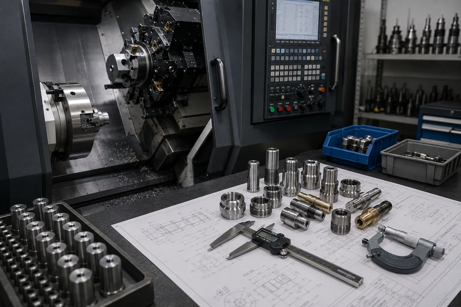
- How a CNC lathe works — chuck, spindle, turret, cutting tools, and typical production flow
- Operations and lathe types — turning, facing, grooving, threading, and multitasking systems
- Design for manufacturability — length-to-diameter ratios, wall thickness, tolerances, and common design mistakes
- Cost, precision, and inspection — how tolerances, material, and cycle time affect manufacturing
- How to quote turned parts — STEP models, technical drawings, quantities, and dimensional requirements
What is CNC turning?
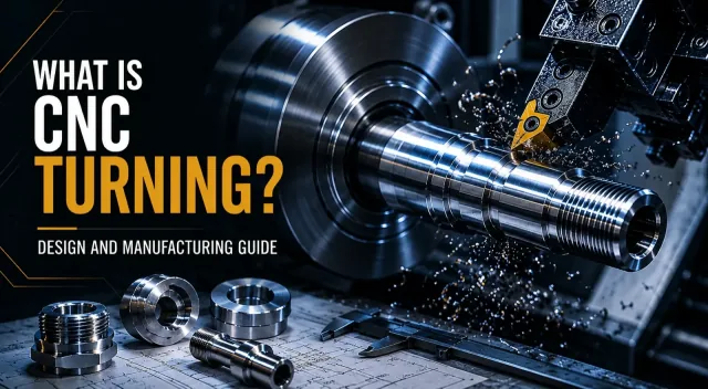
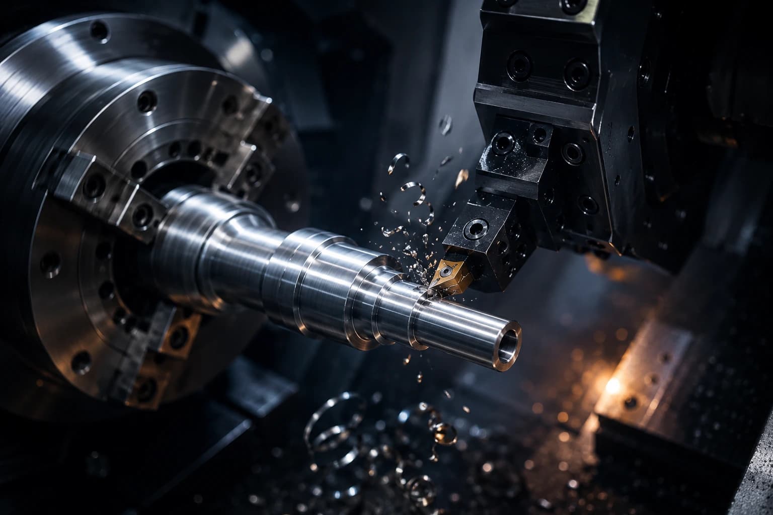
CNC turning is a subtractive manufacturing process used to produce cylindrical and rotational components with high dimensional precision and repeatability. During the process, the part rotates at high speed while cutting tools remove material in a controlled way to generate diameters, faces, grooves, threads, and other functional geometries.
Unlike processes where the tool provides the main cutting motion, in turning the part rotates on its own axis. That makes the CNC lathe especially efficient for producing shafts, bushings, adapters, hydraulic connections, mechanical components, and parts where concentricity and dimensional control matter.
On a conventional lathe, much of the motion and adjustment depends directly on the operator. A CNC lathe, by contrast, runs automated operations through computer numerical control, enabling repeatable parts with less variation between components and better stability during production.
Because of this automation, CNC turning is widely used for prototypes, low-volume production, and repeatable manufacturing across industries such as industrial automation, medical devices, aerospace, automotive, and general manufacturing.
The process also allows multiple operations in a single setup, reducing alignment errors and improving manufacturing efficiency. Depending on lathe configuration, operations such as turning, facing, boring, grooving, threading, and part-off can be performed without moving the part between machines.
For components where the central axis defines mechanical function, CNC turning is often a faster, more repeatable, and more cost-effective solution than other manufacturing approaches.
How does a CNC lathe work?
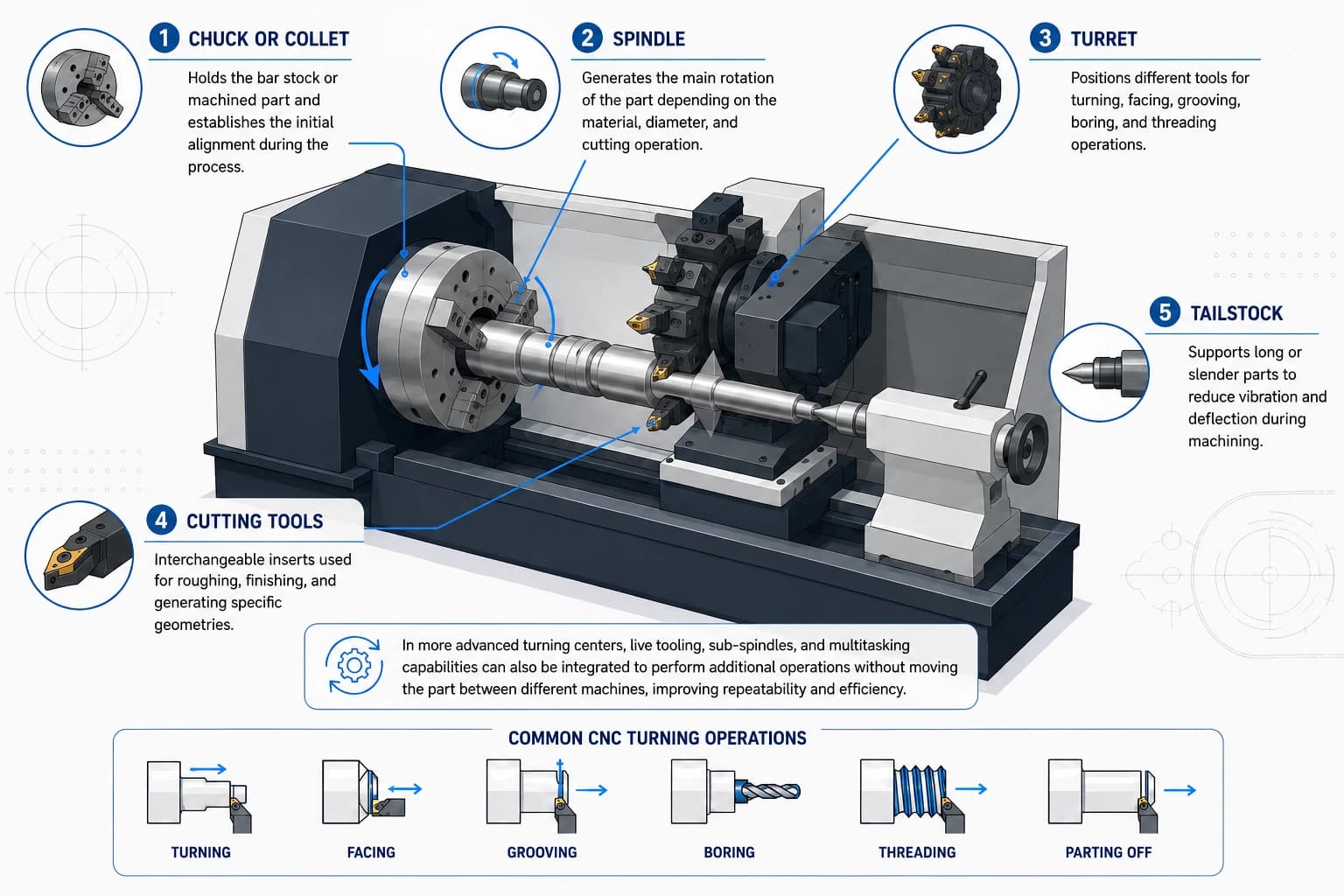
A CNC lathe coordinates rotation, workholding, tool feed, and material removal through numerically controlled automated sequences. During the process, the part rotates on its axis while different cutting tools advance precisely to generate diameters, faces, threads, grooves, and other functional geometries.
The combination of mechanical stability, repeatable programming, and dimensional control enables parts with good concentricity, repeatability, and consistent finishes in both prototypes and production.
Depending on machine configuration, a CNC lathe can integrate multiple operations in one setup, reducing alignment errors and shortening production time. That helps improve precision between critical features and simplifies manufacturing for complex mechanical components.
Main components
- Chuck or collet — holds bar stock or the machined part and sets initial alignment during the process
- Spindle — provides main part rotation based on material, diameter, and cutting operation
- Turret — positions different tools for turning, facing, grooving, boring, and threading
- Cutting tools — indexable inserts used for roughing, finishing, and specific geometries
- Tailstock — supports long or thin parts to reduce vibration and deflection during machining
More advanced turning centers may also integrate live tooling, sub-spindles, and multitasking capabilities that allow additional operations without moving the part between machines. That reduces error stack-up, improves repeatability, and speeds production.
Typical manufacturing flow
- Workholding — selecting the clamping system based on diameter, length, geometry, and stock to remove
- Initial roughing — fast material removal to approach final part shape and dimensions
- Finishing passes — precision passes to control diameters, faces, radii, chamfers, and surface finish
- Boring and threading — functional holes and threads per assembly requirements
- Part separation — final cutoff when manufacturing from continuous bar stock
- Dimensional inspection — validation of critical diameters, concentricity, threads, and functional features before release
In industrial manufacturing, a top priority is reducing setup changes and maintaining consistent references throughout the process. Minimizing re-clamping improves concentricity, repeatability, and alignment between critical features.
When a component combines cylindrical geometry with side operations, off-center holes, or additional machined surfaces, mill-turn machining may be the right choice to integrate multiple operations in one manufacturing setup.
Common CNC turning operations
A turned part is rarely made in a single operation. In most industrial projects, the process combines different machining strategies to generate diameters, faces, threads, bores, and functional geometries within one manufacturing setup.
Integrating multiple operations in one setup helps improve concentricity, reduce alignment errors, and accelerate production time.
These are some of the most common operations in CNC turning for industrial components, prototypes, and repeatable production:
- External turning — OD diameters with dimensional control and consistent surface finish
- Facing — end faces perpendicular to the axis for length and flatness control
- Grooving — retention grooves, tool reliefs, and functional channels
- Boring — precision inner diameters and bores
- Threading — internal or external threads for mechanical and hydraulic connections
- Axial drilling — holes generated on the same part reference axis
- Part-off — final separation when manufacturing from continuous bar stock
Depending on component complexity, some machines also integrate side operations or additional machining through live tooling. That allows more complete parts without moving the component between different manufacturing centers.
Types of CNC lathes
Lathe configuration directly affects precision, geometry complexity, production time, and how many operations can be integrated in one setup. Not every component needs the same machine: a simple cylindrical part may run efficiently on a standard lathe, while more complex geometry may require multitasking or specialized configurations.
Choosing the right lathe type improves manufacturability, reduces setup changes, and maintains better alignment between critical features during production.
- Two-axis CNC lathe — used for simple rotational parts with diameters, faces, grooves, and threads on the same axis
- Live-tooling lathe — integrates drilling, milling, and side operations without moving the part to another machine
- Mill-turn machining — combines turning and milling in one setup to reduce re-clamping and error accumulation
- Swiss-type machining — designed for small, long, or thin parts where stability and repeatability are critical
When the part is mostly cylindrical, CNC turning is often the most efficient solution for cost and production time. If the component combines side geometry, prismatic surfaces, or multiple off-axis operations, evaluate *mill-turn* or Swiss-type machining based on size, complexity, and required tolerances.
Advantages of CNC turning
CNC turning is one of the most efficient processes for producing cylindrical components with precision and repeatability. Because the part rotates continuously on the same reference axis, the process maintains good concentricity, dimensional stability, and competitive production times even in repeatable manufacturing.
In many industrial applications, CNC turning also reduces operation count, simplifies manufacturing, and improves consistency between parts compared with strategies that require multiple setups or different machining processes.
- High repeatability — validated programs for prototypes and repeatable lots with less dimensional variation
- Excellent concentricity — diameters, faces, and related geometry share the same rotation axis during manufacturing
- Efficient production — competitive cycle times for rotational and cylindrical components
- Good surface finish — consistent surfaces across many industrial materials
- Fewer setups — multiple operations can run in one machining configuration
- Continuous bar production — ideal for repeatable small and medium components with good material efficiency
- Production scalability — same process from prototypes through low and medium volume
CNC turning applications
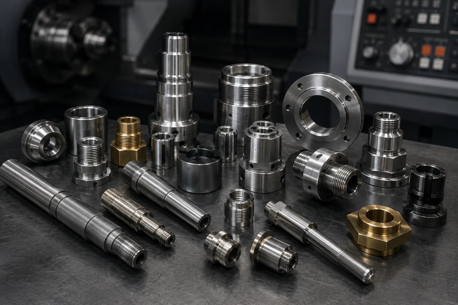
CNC turning is part of many industrial supply chains that require cylindrical components with dimensional precision, repeatability, and good surface finish. Because it is efficient for rotational geometry, the process is used for prototypes and repeatable production of mechanical parts, connections, motion systems, and assembly components.
The ability to maintain concentricity, control diameters, and produce repeatable parts makes CNC turning widely used in industrial automation, general manufacturing, hydraulic systems, medical devices, aerospace, and specialized machinery.
- Shafts and spacers — components for motion transmission, actuators, and rotating systems
- Bushings and bores — parts with controlled inner diameters for mechanical assemblies and wear reduction
- Adapters and connectors — cylindrical and threaded interfaces for mechanical and hydraulic systems
- Hydraulic components — bodies, fittings, and sealing elements with critical dimensional requirements
- Medical and aerospace devices — machined parts with high repeatability and controlled dimensional inspection
- Industrial automation — pins, fixturing, precision hardware, and mechanical integration components
- General manufacturing — replacement parts, functional components, and repeatable production for industrial machinery
Depending on part complexity, CNC turning can also be combined with other manufacturing processes to integrate side geometry, additional surfaces, or more complex mechanical features in the same component.
Design for manufacturability in CNC turning
A well-built CAD model does not always mean the part will be easy, fast, or economical to manufacture. In CNC turning, manufacturability depends on stability during cutting, workholding strategy, tolerances, geometry, and relationships between diameters and lengths.
Applying DFM principles early helps reduce cycle time, simplify inspection, improve repeatability, and avoid dimensional issues during production.
Length-to-diameter ratio and stability
Long, thin parts are more prone to vibration and deflection during machining. When the length-to-diameter ratio is high, maintaining concentricity, surface finish, and tight tolerances becomes more difficult.
In these cases, additional supports, special cutting strategies, or processes designed for slender, high-precision parts may be required.
Thin walls also need special attention. Excessive clamping forces or aggressive cutting parameters can deform the part during manufacturing, affecting critical dimensions and repeatability between components.
Radii, transitions, and functional geometry
Smooth transitions between diameters improve machining stability and reduce stress concentration at abrupt geometry changes. Consistent radii also simplify manufacturing and avoid unnecessarily complex operations.
For threaded geometry, clearly define pitch, functional thread length, and assembly requirements. Avoid hard-to-machine or hard-to-inspect configurations when they do not add real functional value.
Tolerances and gripping zones
Not every dimension needs the same precision level. Applying tight tolerances only on functionally important features helps reduce machining time, simplify inspection, and keep manufacturing costs efficient.
In many industrial projects, general tolerances are enough for non-critical surfaces, while assembly diameters, bores, or alignment zones need tighter dimensional control.
It is also important to consider how the part will be held during the process. Designing clean gripping zones and geometries compatible with workholding systems improves stability, repeatability, and precision during manufacturing.
For components with more complex dimensional requirements, also see our CNC machining tolerances guide.
Common design mistakes in CNC turning
Many manufacturing problems come from design decisions that complicate workholding, stability, inspection, or machining time — not from machine capability. Catching these issues early reduces cost, improves repeatability, and avoids rework during production.
- Unnecessarily tight tolerances — demanding high precision everywhere increases machining and inspection time without real functional benefit
- Walls too thin — cutting and clamping forces can deform the part and affect dimensional stability
- Hard-to-machine geometry — complex transitions, limited access, or special features may require extra tools and setups
- Ignoring vibration and deflection — long or slender parts are more sensitive to deviation during machining
- Over-specified threads and details — excessively complex specifications increase manufacturing and inspection difficulty
- No workholding strategy — some geometries limit process stability and make concentricity harder to maintain
- Hard-to-inspect dimensions — complicated features increase metrology time and interpretation risk
In many cases, small design adjustments can significantly simplify manufacturing without affecting component function. A manufacturability review before releasing production helps identify dimensional risks, reduce unnecessary operations, and improve overall process efficiency.
Tolerances in CNC turning
CNC turning can maintain good dimensional repeatability on cylindrical geometry because the part rotates continuously on the same reference axis during machining. When workholding and manufacturing strategy are stable, the process can control inner and outer diameters and machined faces with high consistency between parts.
On rotational components, concepts such as concentricity, radial runout, and alignment between diameters are especially important because they directly affect assembly, vibration, wear, and mechanical function. This is common on shafts, bores, adapters, connections, and transmission components.
Achievable tolerances depend on geometry, part length, material, cutting stability, surface finish, and inspection method. In many industrial projects, the best strategy combines general tolerances with a small set of critical dimensions clearly identified on the technical drawing.
Applying precision only where it adds functional value helps reduce machining time, simplify inspection, and keep manufacturing costs efficient.
Geometric specifications also help communicate how the part should behave during assembly and operation. Features related to position, perpendicularity, and alignment establish clearer dimensional criteria between design, manufacturing, and inspection.
As required precision increases, manufacturing time, inspection complexity, and the need for more controlled finishing strategies also increase. That is why realistic tolerances are one of the most important decisions for balancing precision, manufacturability, and cost.
For deeper guidance on dimensional specification, inspection, and manufacturability, see our CNC machining tolerances guide.
Common materials for CNC turning
Material behavior directly affects dimensional stability, surface finish, cutting speed, and repeatability during machining. Some materials allow faster processes and more consistent finishes; others require more controlled cutting strategies to maintain precision and tool life.
In CNC turning, the most used materials include aluminum, carbon steels, stainless steels, titanium, and engineering plastics, depending on mechanical application, strength requirements, and operating conditions.
- Aluminum — used in prototypes, lightweight components, and parts with good machinability
- Carbon steels — common in mechanical components, shafts, and structural parts
- Stainless steels — used in corrosive or demanding industrial environments
- Titanium — employed in high-performance industries requiring strength and low weight
- Engineering plastics — used in functional components, insulators, and low-friction applications
Each material responds differently during machining and can affect tolerances, cycle time, surface finish, and manufacturing strategy. Also explore our materials guide to compare mechanical properties, industrial applications, and compatibility with different fabrication processes.
How CNC turning affects cost and lead time
The cost of a turned part depends on more than material removed. Factors such as geometry, machining stability, tolerances, workholding strategy, and inspection complexity directly affect production time and final price.
In many industrial projects, small differences in design or dimensional specification can significantly change cycle time and overall process complexity.
- Material — availability, hardness, and machining behavior affect cutting speed and tool wear
- Machining time — number of operations, depth of cut, and required finish directly impact cycle time
- Tolerances and precision — critical dimensions, alignment, and geometric requirements increase manufacturing and inspection time
- Workholding complexity — long, thin, or difficult-to-hold parts need more controlled manufacturing strategies
- Secondary processes — surface treatments, coatings, or extra inspection add time and cost
- Part quantity — single prototypes and repeatable production have different manufacturing strategies and costs
Reducing unnecessary operations, applying realistic tolerances, and simplifying geometry improves manufacturability and keeps lead times competitive.
To go deeper on optimization and pricing factors, see our CNC machining cost guide.
Inspection and quality control
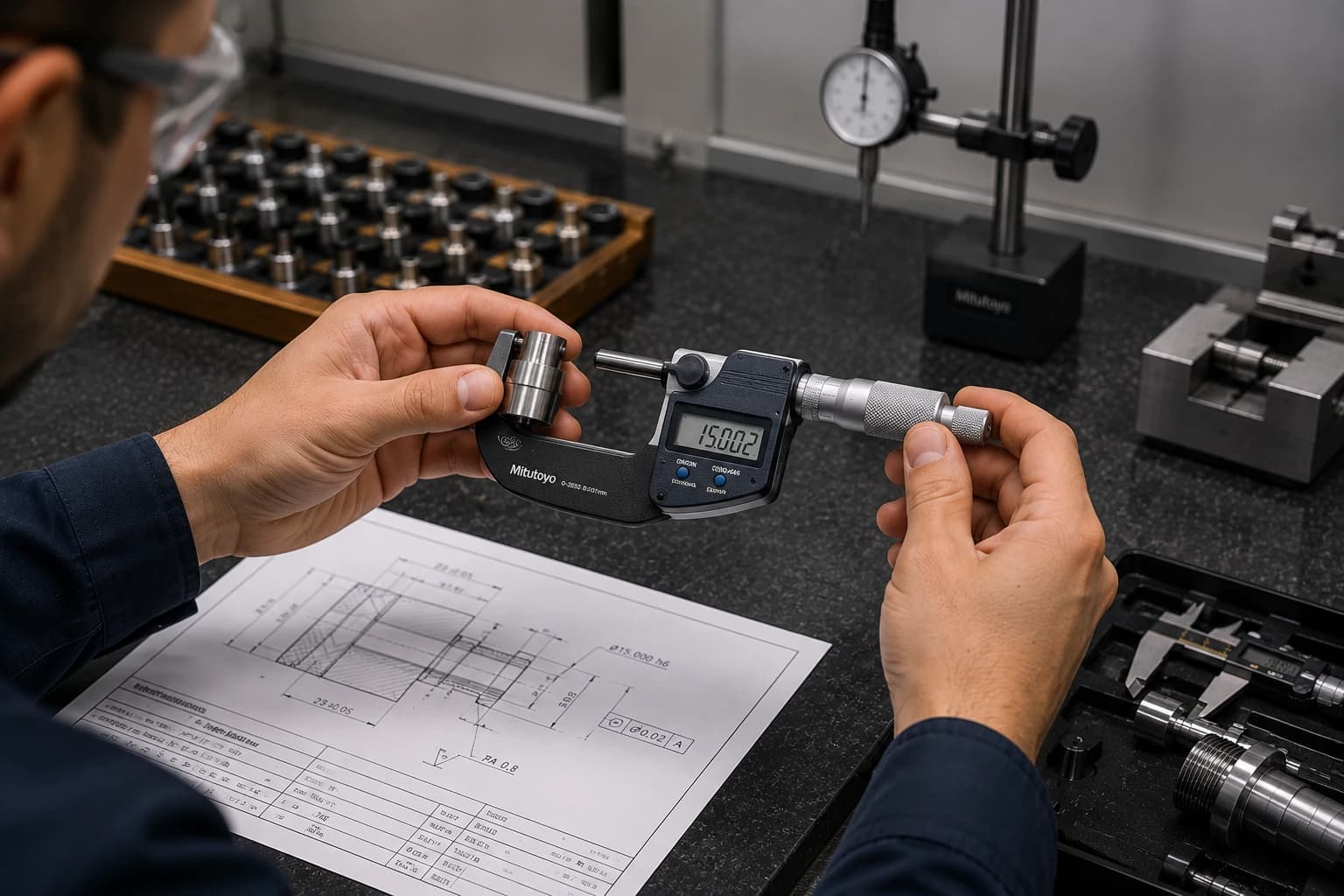
Dimensional inspection in CNC turning focuses mainly on features that affect fit, alignment, and mechanical function. Diameters, lengths, threads, and alignment between surfaces are usually the most important elements when validating industrial parts.
The inspection method depends on component complexity, required tolerances, and the level of documentation requested for the project.
- Micrometers and calipers — used to validate diameters, thicknesses, and functional dimensions
- Coordinate measuring machines — used when the project requires advanced dimensional validation or many related features
- Runout and alignment verification — important on shafts, bores, and rotational components
- Thread inspection — validation with gauges and checking tools per component specification
- Dimensional reports — documentation for production validation, first articles, or critical industrial programs
Clearly identifying critical characteristics on the technical drawing simplifies inspection and reduces validation time during production. If your project requires dimensional documentation or specific validation, note it when quoting through our request a quote page.
How to prepare files to quote CNC turning
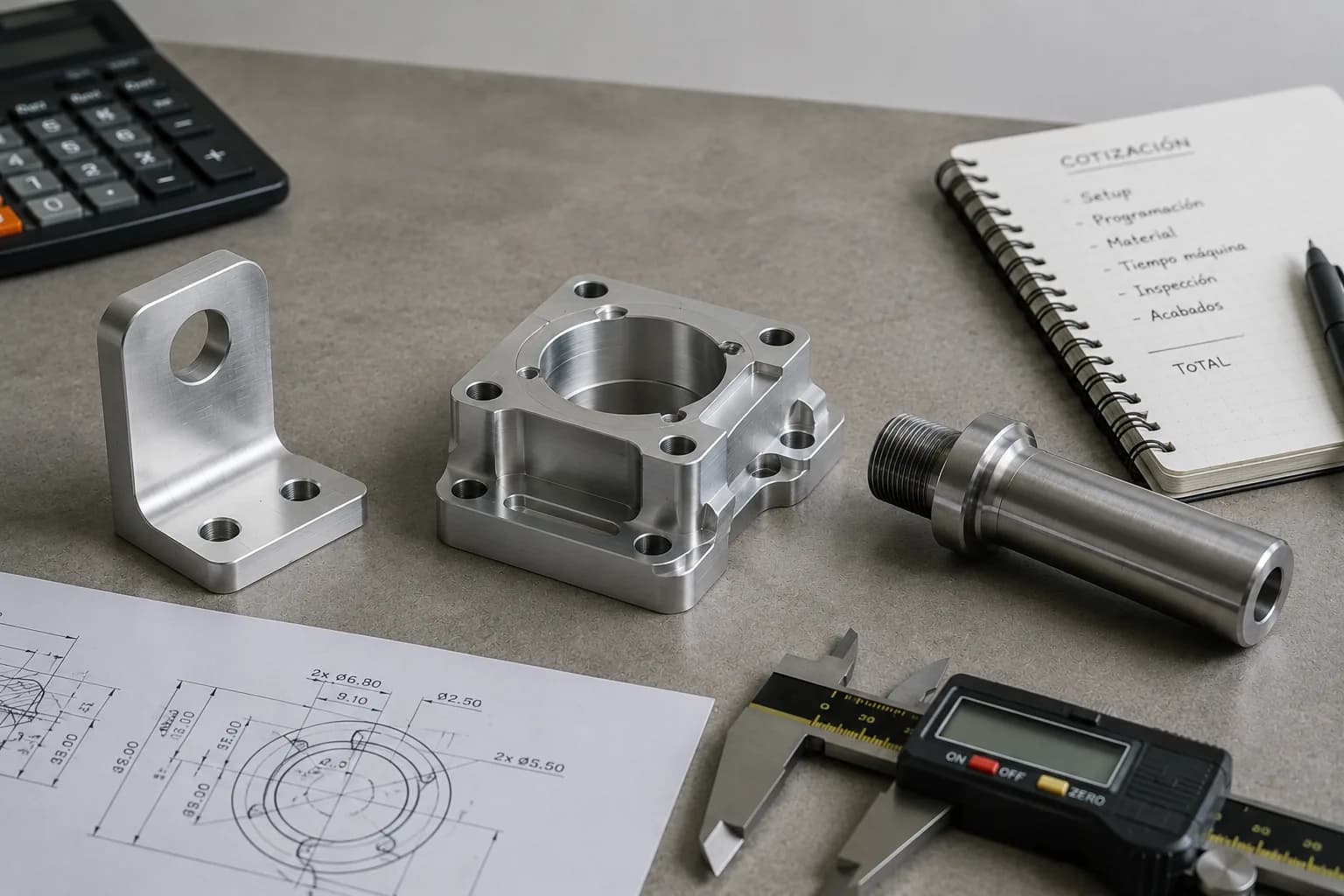
An accurate quote depends largely on the technical information sent at the start of the project. A well-prepared file package reduces review time, avoids unnecessary clarifications, and allows faster evaluation of manufacturability, tolerances, and production strategy.
Beyond the 3D model, include functional information related to critical dimensions, finishes, quantities, and inspection requirements.
For a more detailed explanation of formats and technical documentation, also see our CAD file to CNC quote guide.
- 3D model — preferably STEP format to review geometry and prepare manufacturing
- PDF technical drawing — critical dimensions, tolerances, threads, finishes, and important manufacturing notes
- Important functional features — assembly diameters, alignment, and relevant geometric requirements for inspection
- Required material — material specification or expected mechanical properties for the application
- Finishes and secondary processes — surface treatments, coatings, or aesthetic requirements
- Part quantity — prototype, low volume, or repeatable production to evaluate manufacturing strategy
Including complete information from the start speeds technical review, reduces dimensional risk, and improves alignment between design, manufacturing, and inspection.
How PREMSA Industries produces turned parts
At PREMSA Industries we manufacture turned components for prototypes, low-volume production, and repeatable manufacturing with a focus on dimensional precision, manufacturability, and functional inspection.
Before production starts, we review geometry, tolerances, material, and manufacturing strategy to identify improvement opportunities and reduce machining risk.
- Functional prototypes — design and geometry validation from early development stages
- Low-volume production — repeatable manufacturing without massive production volumes
- Validated manufacturing programs — stable processes to improve repeatability between parts
- Manufacturability review — analysis of geometry, tolerances, and stability during machining
- Dimensional support and inspection — alignment between technical drawing, manufacturing process, and dimensional validation
Depending on component complexity, we run CNC turning with live tooling to optimize manufacturing, precision, and lead time.
Request a quote with your 3D model and technical drawing, or contact us for projects with special dimensional or geometric requirements.
CNC turning — frequently asked questions
Practical answers for engineering, manufacturing, and purchasing on precision, materials, tolerances, and turned part production.
- What parts can be made with CNC turning?
- CNC turning is mainly used for cylindrical and rotational components such as shafts, bushings, adapters, connectors, bores, spacers, and threaded parts. It can also be combined with other processes when the part needs additional geometry or side features.
- How precise can CNC turning be?
- Precision depends on geometry, part length, material, machining stability, and inspection method. Many industrial projects control critical dimensions with specific tolerances while the rest of the part uses general tolerances to balance cost and manufacturability.
- Which materials work best for turned parts?
- Materials with good machinability often offer more efficient production and more consistent finishes. Components in higher-strength or special-application materials are also possible with more controlled machining strategies per project requirements.
- How do tolerances affect the cost of a turned part?
- As required precision increases, machining time, inspection complexity, and the need for more controlled finishing also increase. Applying tight tolerances only on functionally important features helps keep costs efficient.
- What information is needed to quote CNC turning?
- Ideally send a 3D model with a technical drawing that includes critical dimensions, tolerances, material, finishes, and quantity. Clear documentation speeds technical review and improves quote accuracy.
- When should mill-turn machining be used?
- When the part combines multiple geometries, side operations, or long thin components, specialized processes can improve stability, reduce re-clamping, and maintain better dimensional repeatability during manufacturing.
CNC turning is mainly used for cylindrical and rotational components such as shafts, bushings, adapters, connectors, bores, spacers, and threaded parts. It can also be combined with other processes when the part needs additional geometry or side features.
Precision depends on geometry, part length, material, machining stability, and inspection method. Many industrial projects control critical dimensions with specific tolerances while the rest of the part uses general tolerances to balance cost and manufacturability.
Materials with good machinability often offer more efficient production and more consistent finishes. Components in higher-strength or special-application materials are also possible with more controlled machining strategies per project requirements.
As required precision increases, machining time, inspection complexity, and the need for more controlled finishing also increase. Applying tight tolerances only on functionally important features helps keep costs efficient.
Ideally send a 3D model with a technical drawing that includes critical dimensions, tolerances, material, finishes, and quantity. Clear documentation speeds technical review and improves quote accuracy.
When the part combines multiple geometries, side operations, or long thin components, specialized processes can improve stability, reduce re-clamping, and maintain better dimensional repeatability during manufacturing.
Conclusion
CNC turning is one of the most widely used manufacturing processes for producing cylindrical components with precision, repeatability, and good dimensional stability. Understanding how geometry, tolerances, workholding strategy, and manufacturability interact helps develop more efficient parts and optimize production time, inspection, and cost.
Applying good design practices early simplifies production, reduces rework, and improves consistency between prototypes and repeatable lots.
At PREMSA Industries we support CNC turning projects for prototypes, low-volume production, and repeatable manufacturing with a focus on manufacturability, dimensional precision, and functional inspection.
Request a quote with your 3D model and technical drawing, or contact our team to validate manufacturability before releasing production.
If you are preparing or optimizing designs, see our CNC machining design guide.

Written by
Adrian Cavazos and the PREMSA Engineering Team
Adrian Cavazos, founder of PREMSA Industries, leads a manufacturing engineering team specialized in CNC turning and milling, 3D printing, and production-ready solutions. The team works closely with customers to optimize designs, improve manufacturability (DFM), and ensure reliable, scalable production from prototypes to volume manufacturing.