
Before quoting
Quick DFM Checklist
Most problems in CNC parts start from the design, not from the machine. Review these points before submitting your quote request to reduce cost, avoid rework and speed up manufacturing.
01
Do not submit a broken or incomplete STEP
Open surfaces, duplicate bodies or corrupt geometry delay programming, CAM and manufacturing review.
02
Define material and condition from the beginning
6061-T6, 304, 4140, PEEK or titanium completely change cutting speed, wear, setup and final cost.
03
Don't put tight tolerances on the entire part
Unnecessary tolerance can multiply inspection, cycle time, rejection and setup complexity without improving functionality.
04
Avoid impossible internal corners
End mills and Cutting tools are round. Radii that are too small require special tools, EDM or much longer machining times.
05
Avoid deep and narrow pockets
Long tools vibrate, lose precision and aggressively reduce cutting speed.
06
Don't design walls too thin
Weak walls vibrate, deform and generate dimensional rejection during milling or turning.
07
Do not make threads deeper than necessary
More depth rarely adds real strength, but does increase the risk of breaking taps and process time.
08
Think about how the piece is going to be held
Without clear gripping areas, machining requires complex clamping tools, more setup and greater dimensional risk.
09
Do not specify premium finish on the entire piece
Applying anodizing, fine Ra or cosmetic finishing in non-functional areas increases cost and delivery time unnecessarily.
10
Include a PDF drawing if there are CTQs or GD&T
Datums, geometric tolerances, and inspection notes must live on the drawing, not just the STEP model.
PREMSA Comparison
Good vs Bad CNC Design
These design decisions directly influence setup, cycle time, inspection, dimensional risk and final cost. Correcting them before submitting your STEP can save days in manufacturing and thousands in production.
Internal Corners and Radii
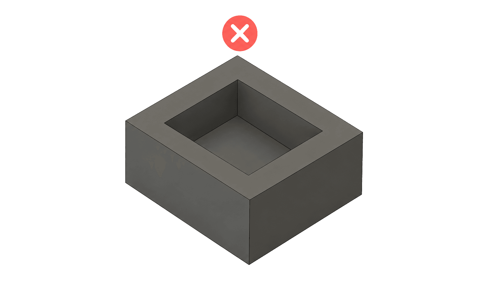
Bad design
- Sharp internal corners at 90° impossible for a standard milling cutter
- Radii smaller than the tool available in the workshop
- May require special tooling, EDM or extremely slow machining
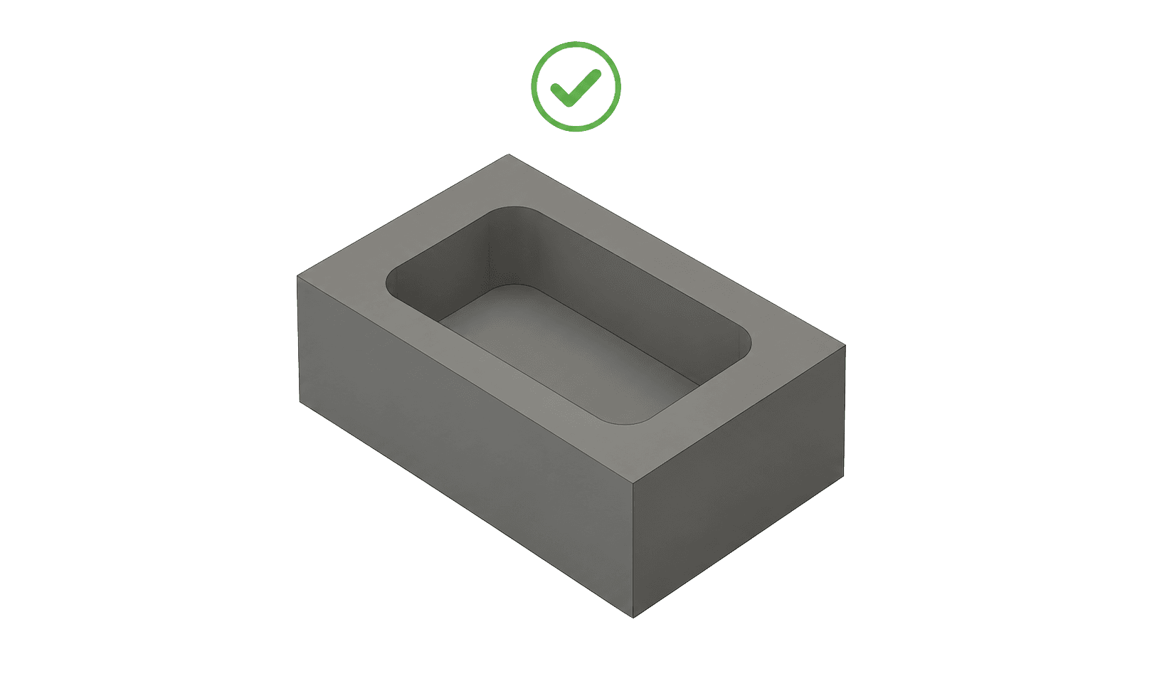
Good design
- Internal radius compatible with standard tool diameters
- Aligned geometry with common CNC milling tooling
- Better cutting stability, lower vibration and shorter cycle time
Deep Pockets
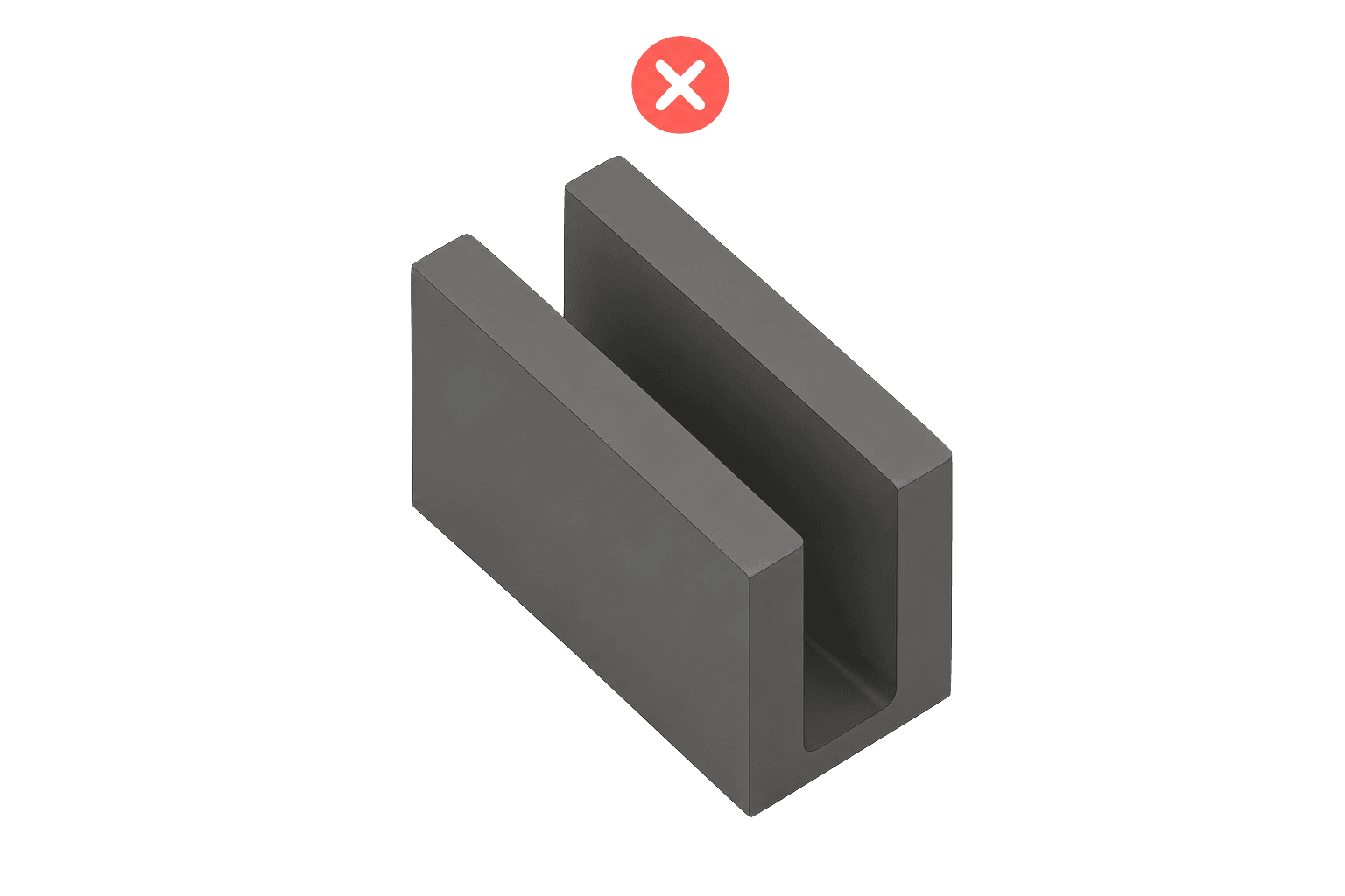
Bad design
- Deep, narrow tunnel pockets
- Too aggressive depth/width ratio
- Long tools prone to vibration, deflection and breakage
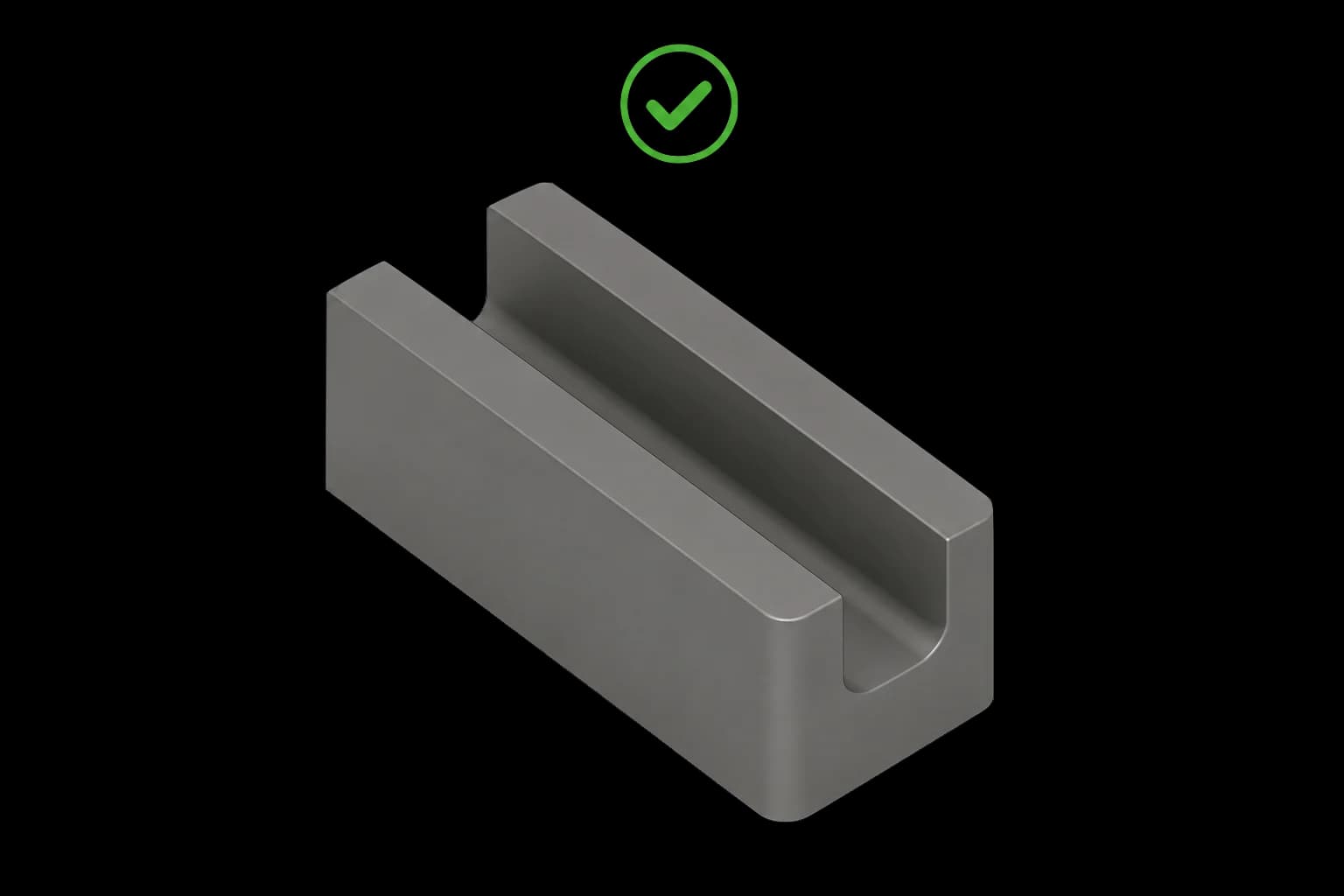
Good design
- Pockets accessible from primary machining orientation
- Moderate depth (goal ≤4× pocket width)
- Bottoms with achievable radius and geometry for efficient milling
General vs Critical Tolerances
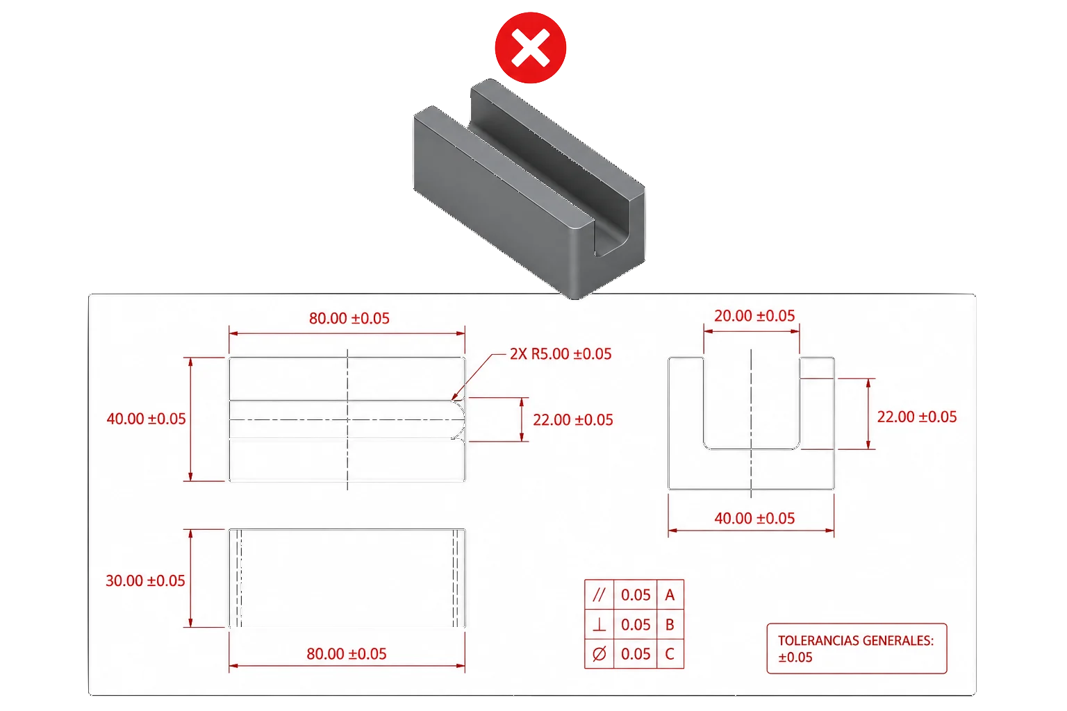
Bad design
- ±0.05 mm applied to the entire piece without functional criteria
- Redundant GD&T on non-critical surfaces
- Mandates CMM inspection and increases rejection without improving real functionality
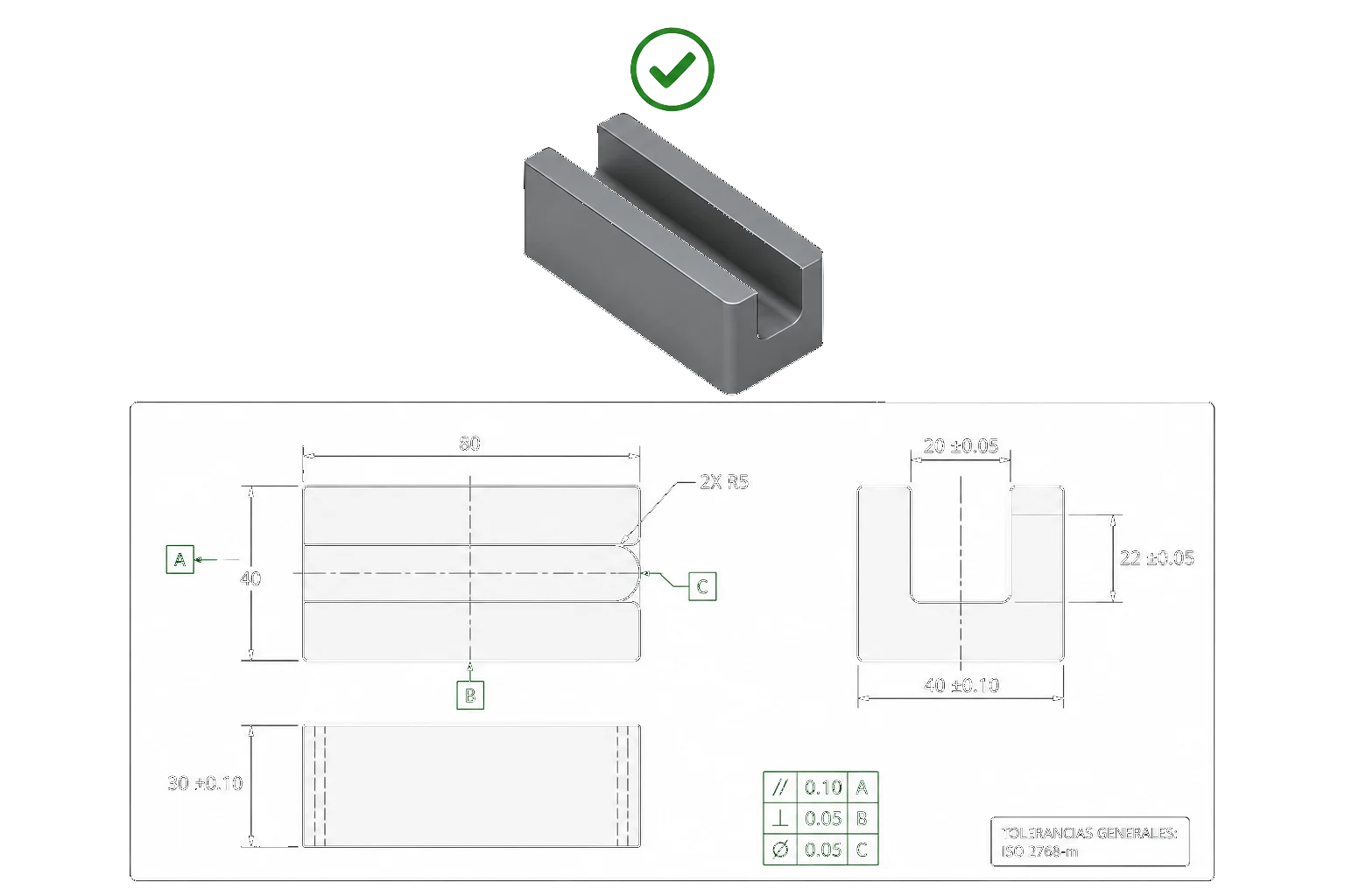
Good design
- ISO 2768-m as general tolerance for non-critical geometry
- Close tolerances only in assembly, alignment or sealing
- Technical drawing with clear CTQs, datums and dimensional priorities
Deep Holes and Threads
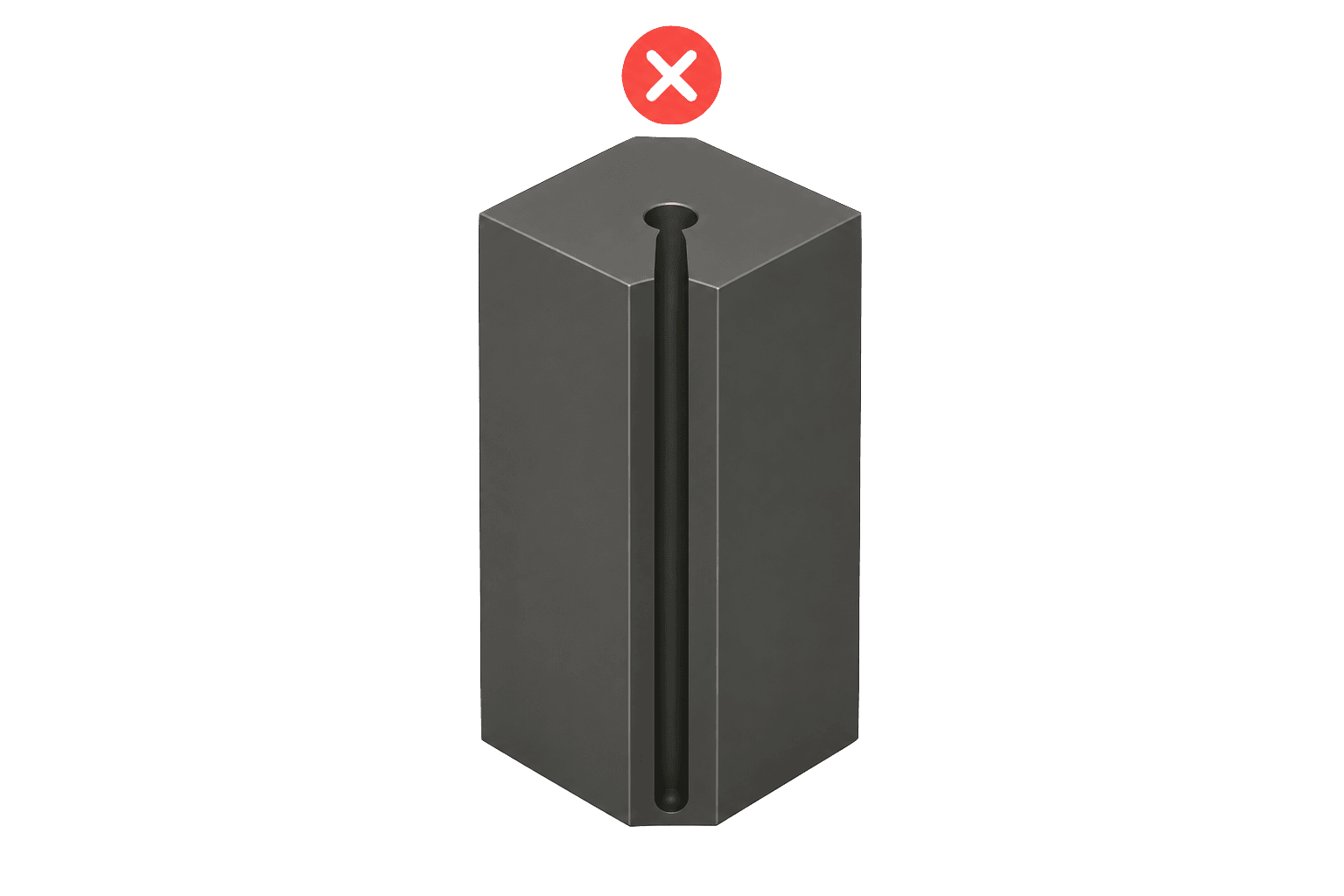
Bad design
- Excessively deep small holes
- Depth/diameter ratio greater than 10×
- Too long blind threads with no real mechanical benefit
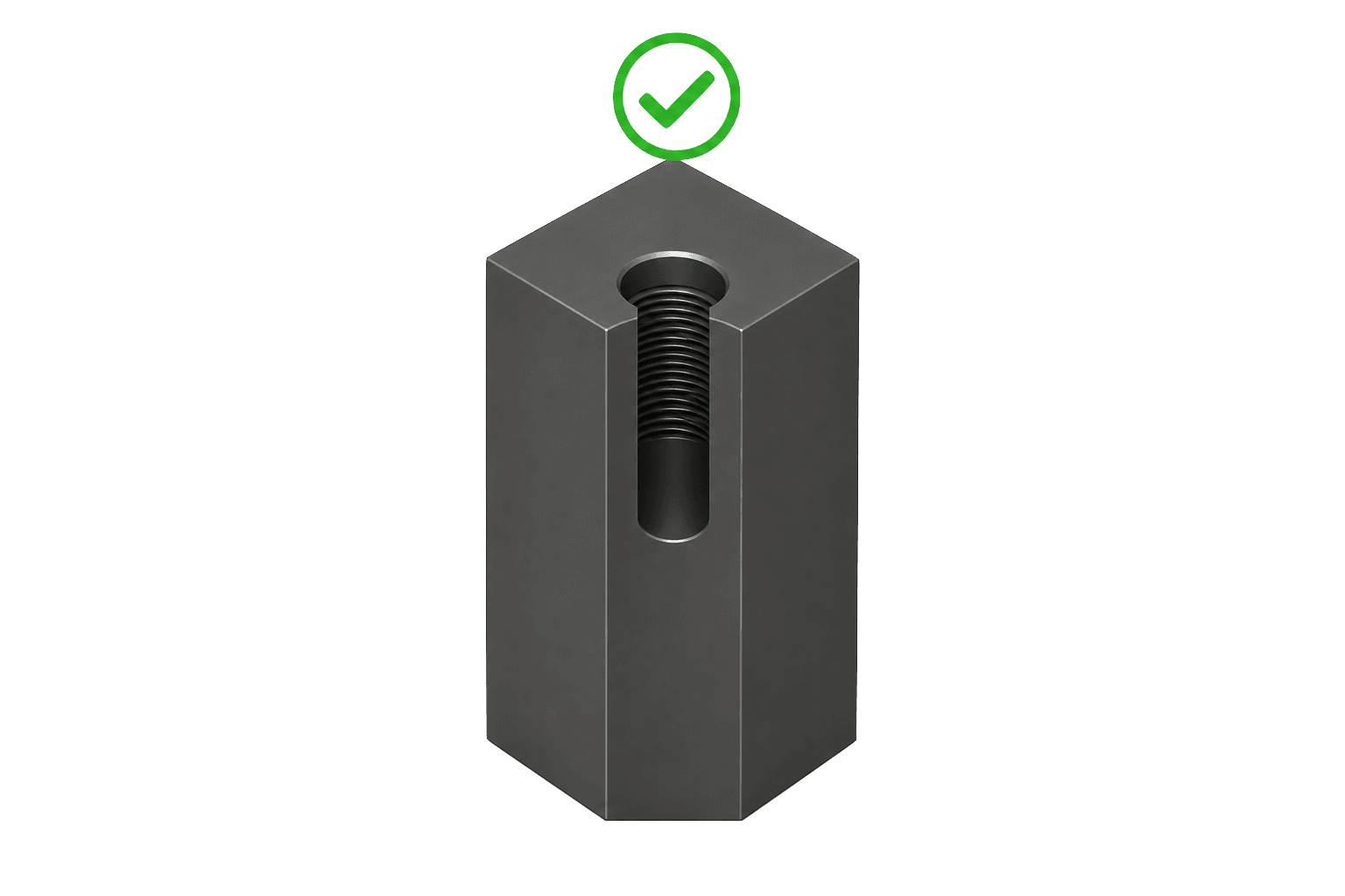
Good design
- Standard drill diameters wherever possible
- Manufacturable depth (goal ≤5× diameter)
- Functional thread engagement (~1.5×–2× screw Ø)
DFM Reference
Practical Limits of CNC Design
These geometric relationships directly influence vibration, cutting stability, tool wear, cycle time and dimensional risk. Designing outside the recommended area normally increases cost, setup, inspection and delivery time.
| Feature | Recommended area | High cost area |
|---|---|---|
| Wall thickness (metal) | ≥1.0mm | ≤0.5mm |
| Wall thickness (plastic) | ≥1.5mm | ≤1.0mm |
| Hole depth | ≤5×Ø | >10× Ø |
| Pocket depth | ≤4× width | >8× width |
| Thread engagement | 1.5×–2× Ø | >3× Ø |
| Minimum internal radius | ≥ Radius of tool | < Radius of tool |
| L/D ratio (turning) | ≤4× | >8× |
Titanium, stainless and engineering plastics typically require more conservative margins. If your part falls within the high cost zone, PREMSA can help you redesign details to improve manufacturing and reduce production costs.
Cost factors
How Design Decisions Affect CNC Cost
In CNC machining, the cost does not depend only on the material or size of the part. Geometry, setup, tolerances, inspection and finishing can double production time even before the first cut.
Details from multiple orientations or too many setups
Titanium, stainless steel or difficult superalloys
Inaccessible geometry that requires 5 axes
Complex GD&T on too many surfaces
Specified cosmetic finish on entire piece
Global closed tolerances without functional criteria
Deep, narrow pockets
Non-standard threads, holes or details
Walls too thin
Dimensions that are difficult to measure or inspect
DFM CNC Rules
Core Design Rules for CNC Machining
These CAD decisions have more impact on cost, cutting stability, setup, inspection and delivery time than almost any other manufacturing detail.
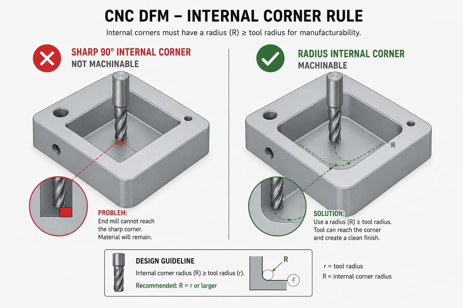
Design Manufacturing Internal Radii
End mills and cutting tools are round. Too tight internal corners require small tools, slow machining or even EDM. Maintaining radii compatible with standard tools reduces vibration, improves cutting stability and speeds up roughing.
Internal radius ≥ tool Radius
Avoid Deep and Narrow Pockets
The deeper and narrower a cavity is, the more difficult it is to evacuate chips and control vibration. Long tools reduce precision, increase vibration and increase cycle time.
Goal ≤4× pocket width
Maintain Realistic Wall Thickness
Thin walls deform during cutting, especially in aluminum, stainless steel and plastics. Vibration and heat can cause dimensional rejection even with correct programming.
≥1.0 mm metal · ≥1.5 mm plastic
Control Depth of Holes
Drills that are too deep require long tools that are prone to deflection and breakage. Extreme depth/diameter ratios increase dimensional risk and process complexity.
≤5× Ø recommended
Do Not Oversize Thread Depth
More depth rarely improves actual resistance. Excessively long threads increase machining time and risk of breaking taps without proportional functional benefit.
1.5×–2× Ø screw
Design with Tool Access in Mind
If the tool doesn't fit easily, the cost goes up. Inaccessible geometries require 5 axes, special tools, EDM or additional setups.
1 ideal main orientation
Minimizes Unnecessary Undercuts
Complex undercuts require T-slot tools, lollipop or special CAM strategies. Each undercut adds risk, setup, and programming time.
Avoid if not functional
Use Fillets and Chamfers Strategically
Controlled chamfers simplify deburring and assembly. External fillets improve ergonomics and reduce sharp edges without complicating manufacturing.
Only where they add value
Avoid Complexity without Real Function
Decorative curves, organic surfaces and redundant details increase CAM programming, inspection and machine time without improving product performance.
Less details = less cost
Reduces Setup Changes
Each additional orientation means more tooling, more alignment, and greater risk of dimensional buildup. Designing multiple details from a single orientation reduces cost and improves repeatability.
Minimize setups
Precision with intent
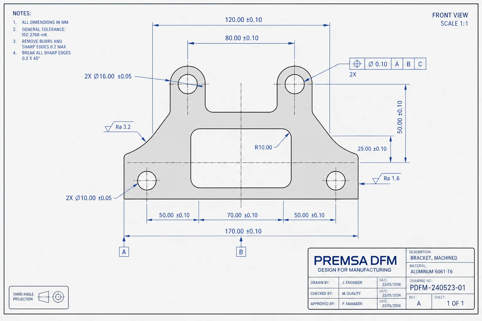
CNC Tolerances
Most parts fail not because of lack of precision, but because of applying precision where it adds no value. Well-defined tolerances reduce setup, simplify inspection and improve manufacturing ability from quote.
General Tolerances vs Critical Tolerances
Not all dimensions need the same level of control. Defines a general tolerance for non-critical geometry and reserves close tolerances only for assemblies, sealing, alignment, or functional surfaces. Applying unnecessary precision throughout the part increases cost, inspection and rejection risk without improving actual performance.
ISO 2768-M — Typical Linear Tolerances
Practical reference for dimensions without individual tolerance on the drawing. Medium class (m) according to ISO 2768-1.
| Nominal range | Tolerance (mm) | Equivalent (in) |
|---|---|---|
| 0.5 – 3mm | ±0.1 | ±0.004 |
| 3 – 6mm | ±0.1 | ±0.004 |
| 6 – 30mm | ±0.2 | ±0.008 |
| 30 – 120mm | ±0.3 | ±0.012 |
| 120 – 400mm | ±0.5 | ±0.020 |
| 400 – 1,000mm | ±0.8 | ±0.031 |
A tolerance of ±0.005 in (±0.13 mm) is often considered relatively fine precision in standard CNC manufacturing. Reserve it only for functional details or assembly criticalities.
Use ISO 2768-M as a Starting Point
ISO 2768-m is a practical default for most milled and turned parts. It allows stable manufacturing without overloading programming, metrology or machine time in non-critical dimensions.
When a Tolerance of ±0.005 Mm Does Make Sense
Slight adjustments, shaft alignment, sealing surfaces, assembly interfaces and repeatable geometry in production often justify tighter tolerances with defined inspection.
When You Really Need Tighter Tolerances
Bearings, precision couplings, valves, critical concentricity or position GD&T require advanced dimensional control, clear datum strategy and more robust inspection.
Why Tight Tolerances Drive Up Costs
More precision means more finishing passes, smaller tools, thermal control, lower cutting speed, CMM inspection, and higher risk of dimensional rejection. An unnecessary tolerance can multiply the cost of the entire part.
What Dimensions Should Be Critical?
- Mating and assembly surfaces
- Bearing, bushing or interference fit adjustments
- Sealing and contact surfaces
- Datums and alignment details
- Relative position between holes or axes
- Assembly Functional Interfaces
CNC milling
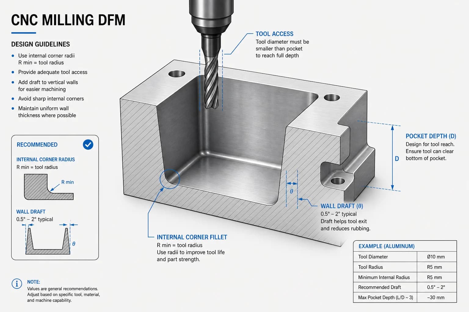
Design Guides for CNC Milling
In CNC milling, the geometry of the part is limited by the actual access of the tool. Depth, orientation, internal radii and number of setups determine whether a part can be produced quickly in 3 axes or will require 5 axes, special tooling and much longer cycle times.
Design Accessible Pockets
Deep, narrow pockets hold long tools prone to vibration and vibration. Keep cavities accessible from the primary orientation and use internal radii compatible with standard end mills.
Avoid Slots That Are Too Narrow
Slots smaller than the available tool diameter require special milling cutters, lower feed rates and considerably higher machining times.
Avoid Excessively Deep Cavities
The deeper the cavity relative to its width, the more difficult it is to evacuate chips and maintain dimensional stability. Consider progressive roughing and finishing instead of an aggressive single pass.
Strengthens Thin Walls
Thin walls vibrate, deform and accumulate heat during cutting. Base radii and correct machining sequences help maintain stability.
Specifies Flatness Only Where It Matters
Large, flat surfaces require finishing passes, thermal control and rigid clamping. Applying unnecessary flatness tolerances increases cycle and inspection time.
Reduces Multi-Face Machining
Each additional orientation means more setups, more alignment, and more dimensional risk. Consolidating details from a single side reduces cost and improves repeatability.
When to Use 3 Axis vs 5 Axis
3 axis is usually the most economical option when details are accessible from above. 5 axes is justified for complex geometries, composite surfaces or significant reduction of setups.
Design with Support in Mind
The piece needs rigid gripping areas. Avoid placing cosmetic or critical surfaces where the jaw or fixture must grip during machining.
Do Not over-Specify Surface Finish
Defines Ra or finish only on functional, visible or sealing faces. Applying a fine finish to the entire piece increases cutting and post-processing time with no real benefit.
CNC turning
Design Guides for CNC Turning
In CNC turning, the axis of rotation naturally defines concentricity, eccentricity and dimensional repeatability. The length/diameter ratio, gripping zones, and off-axis complexity determine whether the part can be efficiently produced on a conventional lathe, mill-turn, or Swiss lathe.
Controls the Length/Diameter Ratio
Long, slender parts are prone to vibration, deflection and chatter. High L/D ratios may require tailstock, steady rest or multiple operations.
Design Around the Turning Datum
Machined details in the same clamping maintain better concentricity and alignment. Changing setups increases the risk of accumulated misalignment.
Do Not Specify Unnecessary Eccentricity
Strict eccentricity on non-functional surfaces requires additional inspection and greater process control without adding real value to the component.
Keep Slots Compatible with Standard Inserts
Grooves that are too narrow or deep require special tools, less feed and greater risk of vibration or breakage.
Use Standard Threads Whenever Possible
Metric, UNC or UNF threads simplify manufacturing, inspection and tool availability. Defines functional hitch class and length.
Avoid Extreme Internal Drilling
Deep holes and small diameters require anti-vibration bars and reduce cutting stability, especially in stainless and titanium.
Design Thicknesses Compatible with Turning
Thin walls are easily deformed by jaw pressure, heat and shear stress. The risk increases significantly in titanium and stainless steel.
Leaves Clean Grip Areas
The lathe needs enough length to hold the workpiece rigidly. Avoid critical details or cosmetic finishes within the jaw area.
When to Use a Swiss Lathe or Mill-Turning
Swiss lathe machining and mill-turning are ideal for long parts, small diameters, side holes, and off-axis geometries that would generate multiple setups on a conventional lathe.
Holes · Threads · Inserts
Design Guides for Holes, Threads and Inserts
Prefer through Holes When Possible
Through holes simplify drilling, chip evacuation and deburring. Blind holes require extra tip depth, chip control and greater dimensional attention.
Consider the Actual Tip of the Drill
The useful depth of a blind hole is always less than the total depth drilled. Ignoring the point angle can leave incomplete threads or detup interferences.
Do Not Oversize Thread Depth
In most alloys, an engagement of 1.5×–2× the screw diameter is sufficient. More depth usually only increases process time and risk of breaking taps.
Uses Standard Diameters and Threads
Metric, UNC and commercial sizes threads simplify quoting, inspection and tool availability. Custom details often require special tooling or slower processes.
Don't Mix NPT with Straight Threads without Analysis
NPT threads seal by conical interference; Metric or straight ones usually require additional O-rings, seals or contact faces.
Define Inserts from the Design
Helicoils and inserts require specific pre-drilling, controlled depth and sufficient space around the detail for safe installation.
Avoid Small and Extremely Deep Holes
Small drills with aggressive depth/diameter ratios are highly prone to deflection, vibration and tool breakage.
CNC materials
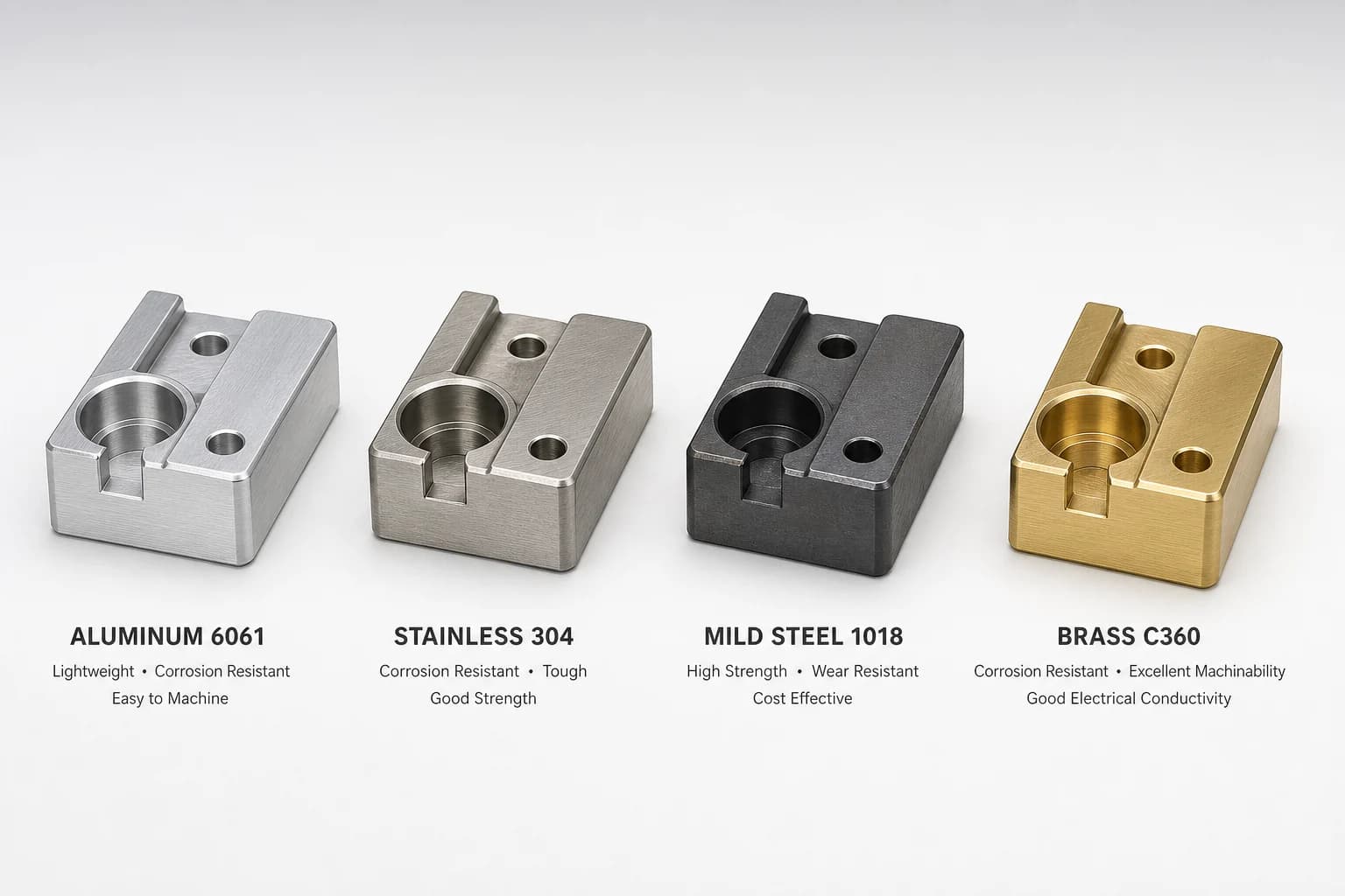
Materials and Machinability
Material selection directly influences cutting speed, tool wear, dimensional stability, inspection and final manufacturing cost.
| Material | Machinability | Cost impact | Dimensional risk | Typical application |
|---|---|---|---|---|
| 6061-T6 Aluminum | Excellent | Low–Medium | Low | Prototypes, tooling, casings and general structural parts |
| 7075-T6 Aluminum | High | Medium | Low–Medium | High strength, aerospace and light tooling |
| 304 stainless steel | Medium | Medium–High | Medium | Food-grade, general corrosion and industrial components |
| 316 stainless steel | Medium–Low | High | Medium | Marine, chemical, medical and corrosive environments |
| 1018 steel | High | Low–Medium | Medium | Structural parts, plates and general components |
| 4140 steel | Medium | Medium | Medium | Axles, gears, load components and treatable parts |
| Brass C360 | Excellent | Medium | Low | Connectors, fittings, valves and precision components |
| Grade 5 Titanium | Difficult | High | High | Aerospace, medical and heavy duty/weight applications |
| Acetal (Delrin) | High | Low–Medium | Medium | Gears, guides and low friction components |
| Nylon | Medium | Low | Medium–High | Bushings, prototypes and non-dimensionally critical parts |
| PEEK | Medium (controlled process) | Very High | Medium | High temperature, chemical, medical and light metal replacement |
Finishes and post-process
How Finishes Affect Manufacturing and Tolerances
The surface finish not only changes appearance. Each process alters dimensions, lead time, masking, inspection and dimensional risk after machining.
| Acabado / proceso | Effect on tolerances | Lead time | Masking |
|---|---|---|---|
| As-machined | Base Dimensional Reference | Minimum lead time | Not required |
| Bead Blasting | May smooth edges and modify Ra | + short | Critical faces or sealing |
| Anodizing | Generates layer growth (typ. ~25 µm) | + medium | Threads, bores and fitting surfaces |
| Powder Coat | Visible thickness on faces and corners | + medium | Mechanical interfaces and threads |
| Passivation | Minimal dimensional impact | + short | Only if there are selective areas |
| Black Oxide | Very thin surface layer | + short | Critical Fitting Surfaces |
| Electropolishing | Removes surface material | + medium | Critical geometric details |
| Plating / Coating | Increases dimensional thickness | + long | Critical on fine tolerances |
Note: Always specify whether critical tolerances apply pre-treatment or post-treatment. Processes such as anodizing, coating or powder painting modify final dimensions and may require masking or compensation in CAD.
Common DFM Problems
Problems That Trigger CNC Costs
Most expensive parts are not difficult because of material or size, but because of design decisions that complicate tooling, setup, inspection and manufacturing.
Problem
Apply close tolerances to the entire part
How to fix it
Use ISO 2768-m as a basis and reserve fine tolerances only for functional or assembly surfaces.
Problem
Design impossible internal corners for a milling cutter
How to fix it
Add spokes compatible with standard tools or document EDM only if strictly necessary.
Problem
Create deep and extremely narrow cavities
How to fix it
Reduce depth, increase width, or split geometry into more accessible features.
Problem
Use thin walls without structural support
How to fix it
Increase thickness, add ribs or select a more stable alloy.
Problem
Design details impossible to inspect
How to fix it
Leaves access for CMM, gauges or measuring instruments from the initial design.
Problem
Choose titanium or stainless steel without real functional requirement
How to fix it
Validates whether aluminum 6061, 7075 or 1018 steel meet performance with much lower cost.
Problem
Specify premium finish on entire piece
How to fix it
Limit anodizing, polishing or fine Ra only to visible or functional areas.
Problem
Forcing too many setups and orientations
How to fix it
Group details from the same face and evaluate 5 axes only when it really reduces complexity.
Problem
Design deep or non-standard threads
How to fix it
Use standard metric or UNC and limit hitch to ~1.5×–2× Ø.
Problem
Send ambiguous or incomplete drawings
How to fix it
Includes material, general tolerance, finishes, datums, CTQs and clear inspection notes.
CNC Quote Package
How to Prepare Files to Quote CNC Parts
A clear request for quotation reduces rework, speeds up manufacturing review and avoids weeks wasted on technical clarifications. Most delays start with incomplete files, ambiguous tolerances, or misaligned revisions.
01
Clean and Consistent STEP
Sends a closed solid in STEP/STP with clear units (mm or inches). Open surfaces, duplicate bodies or incorrect scales delay CAM and programming.
02
PDF Drawing with Manufacturing Intent
Includes necessary views, functional dimensions, general tolerance, datums, finishes and critical notes for inspection.
03
Fully Defined Material
Specify alloy, thermal condition and standard when applicable (ASTM, AMS, MIL, etc.). 'Aluminum' or 'stainless' is not enough to quote correctly.
04
Clarify If It Is a Prototype or Production
The quantity changes setup strategy, tooling, inspection and unit price. A prototype part is not priced the same as a recurring lot.
05
Define Finishing Only Where It Matters
Indicates Ra, anodizing, bead blast, powder coating or plating only in functional, cosmetic or sealing areas.
06
Mark CTQs and Avoid Conflicting Tolerances
Use general tolerance for common geometry and define precision only in functional or assembly dimensions.
07
Maintain Revision Traceability
The revision number must match between STEP, drawing and bill of materials to avoid manufacturing obsolete geometry.
08
Document Critical Constraints
Notes such as 'no bite', 'no cosmetic marks', 'M4 Helicoil' or 'certified material' must be explicit from the quote.
09
Clarifies Inspection Requirements
FAI, dimensional reports, PPAP or CMM must be specified from the RFQ to avoid later scope changes.
Common Mistake
Sending only the STEP without a technical drawing usually raises doubts regarding tolerances, finishes, datums and functional intention.
PREMSA Recommendation
The best RFQ combines clean STEP, clear drawing and minimal but precise functional notes.

Inspection and quality
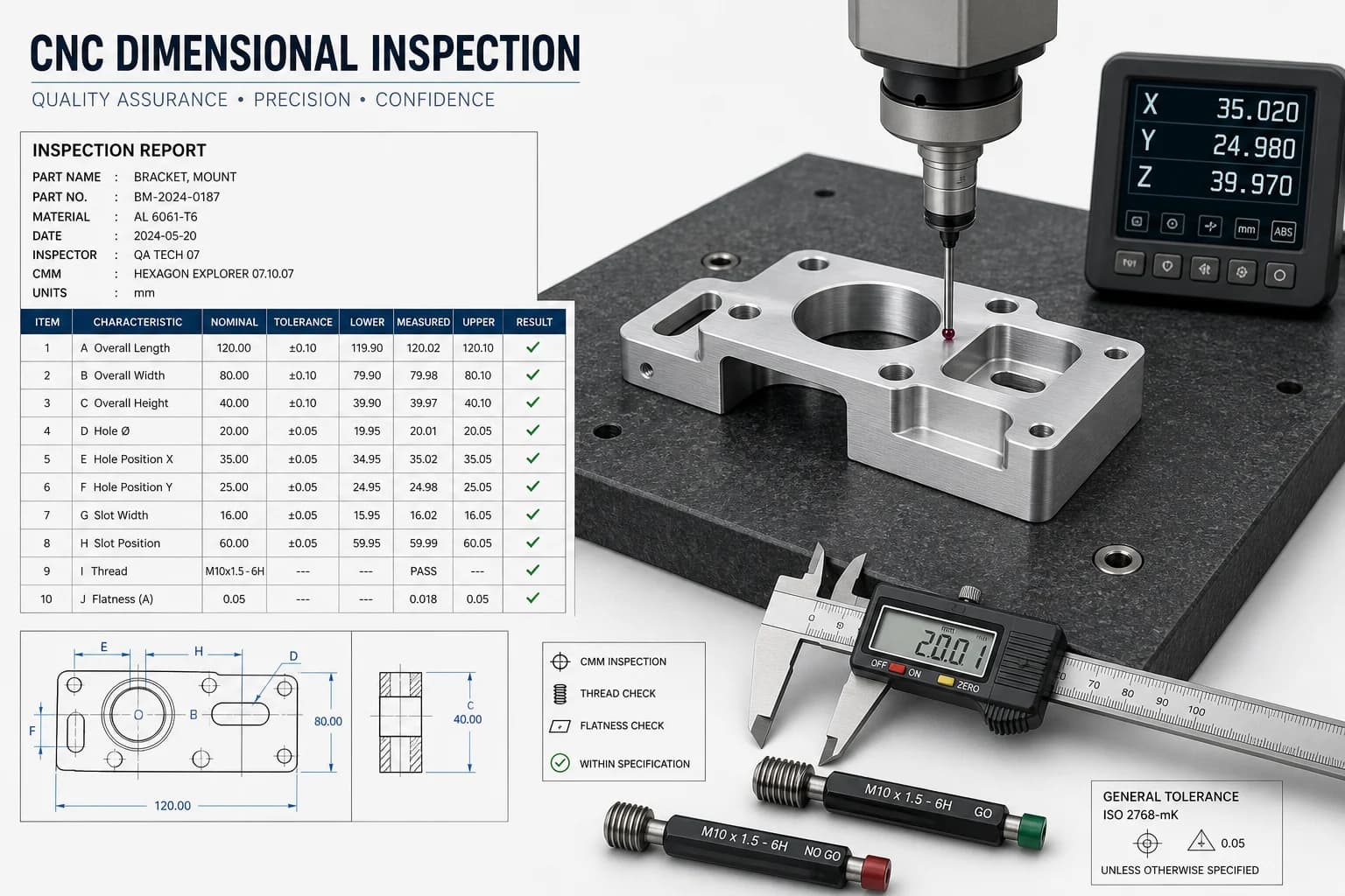
How to Align Inspection with Actual Tolerances
Each tolerance you add also defines measurement time, inspection strategy and quality cost. Not all dimensions require CMM or full reporting.
Calipers
Ideal for general dimensions, quick validation in production and geometry with moderate tolerances.
Micrometers
They allow diameters and thicknesses to be controlled with greater resolution than a standard caliper.
Go/No-Go Gauges
The fastest and most consistent way to validate functional threads in repetitive production.
CMM
Required for complex GD&T, true position, concentricity and geometry difficult to measure manually.
First Article Inspection (FAI)
Validates the first manufactured item against the drawing, tolerances and dimensional requirements before releasing production.
Dimensional Reports
They document actual measurements against critical levels for audit, PPAP or quality traceability.
CTQs
Characteristics critical to quality must be explicitly identified to focus inspection where it really matters.
Common Mistake
Request complete inspection of the entire part when only a few dimensions are functionally critical.
PREMSA Recommendation
Defines clear CTQs and allows general tolerances on the rest of the geometry to reduce metrology time and overall cost.
Frequently Asked Questions About CNC Design
Direct answers to define tolerances, geometry, and quote package requirements without slowing manufacturing.
- What general tolerance should I use for a standard CNC machined part?
- For most CNC machined components, ISO 2768-m is a practical default for non-critical geometry. It keeps manufacturing stable and cost-efficient without overloading inspection or machining time. Then apply tighter tolerances only on CTQs, sealing surfaces, bearing fits, alignment features, or assembly-critical dimensions.
- When is a STEP file enough, and when do I also need a PDF drawing?
- A clean STEP file is often enough for simple prototype geometry with standard tolerances. However, if the part includes GD&T, critical dimensions, cosmetic requirements, thread specifications, inspection instructions, or assembly-related intent, a PDF drawing becomes essential. The STEP model defines geometry; the drawing defines manufacturing and inspection intent.
- What thread depth is actually recommended in CNC machining?
- In most materials, a thread engagement of approximately 1.5× to 2× the nominal screw diameter provides more than enough mechanical strength. Deeper threads rarely improve performance but significantly increase tapping time, chip evacuation difficulty, and risk of broken taps—especially in blind holes or small diameters.
- Why do deep pockets increase CNC machining cost so aggressively?
- Deep and narrow pockets force the use of longer cutting tools, which are more prone to vibration, deflection, chatter, and tool breakage. To maintain dimensional stability, the machine often requires lower feed rates, additional roughing passes, slower stepovers, and longer cycle times. The deeper the cavity relative to its width, the more expensive and unstable the process becomes.
- Should I apply tight tolerances across the entire CNC part?
- Usually no. Applying unnecessarily tight tolerances globally increases machining passes, metrology time, CMM inspection, scrap risk, and manufacturing complexity without improving actual functionality. A better DFM strategy is to use general tolerances for secondary geometry and reserve precision only for functional, mating, sealing, or alignment-critical features.
- What information helps PREMSA quote CNC parts faster?
- The fastest quote packages typically include a clean STEP model, PDF drawing (if applicable), material specification, quantity, finish requirements, and clearly identified CTQs or inspection notes. When manufacturing intent is clear from the start, DFM review, pricing, programming, and production release become significantly faster and more accurate.
For most CNC machined components, ISO 2768-m is a practical default for non-critical geometry. It keeps manufacturing stable and cost-efficient without overloading inspection or machining time. Then apply tighter tolerances only on CTQs, sealing surfaces, bearing fits, alignment features, or assembly-critical dimensions.
A clean STEP file is often enough for simple prototype geometry with standard tolerances. However, if the part includes GD&T, critical dimensions, cosmetic requirements, thread specifications, inspection instructions, or assembly-related intent, a PDF drawing becomes essential. The STEP model defines geometry; the drawing defines manufacturing and inspection intent.
In most materials, a thread engagement of approximately 1.5× to 2× the nominal screw diameter provides more than enough mechanical strength. Deeper threads rarely improve performance but significantly increase tapping time, chip evacuation difficulty, and risk of broken taps—especially in blind holes or small diameters.
Deep and narrow pockets force the use of longer cutting tools, which are more prone to vibration, deflection, chatter, and tool breakage. To maintain dimensional stability, the machine often requires lower feed rates, additional roughing passes, slower stepovers, and longer cycle times. The deeper the cavity relative to its width, the more expensive and unstable the process becomes.
Usually no. Applying unnecessarily tight tolerances globally increases machining passes, metrology time, CMM inspection, scrap risk, and manufacturing complexity without improving actual functionality. A better DFM strategy is to use general tolerances for secondary geometry and reserve precision only for functional, mating, sealing, or alignment-critical features.
The fastest quote packages typically include a clean STEP model, PDF drawing (if applicable), material specification, quantity, finish requirements, and clearly identified CTQs or inspection notes. When manufacturing intent is clear from the start, DFM review, pricing, programming, and production release become significantly faster and more accurate.
Quick answer: what is CNC design for manufacturability?
CNC DFM means designing parts so mills, lathes, and inspection can produce them without extra setups, special tooling, or unnecessary tight tolerances. Most CNC cost problems start in CAD — not on the machine.
PREMSA's guide covers practical rules: ISO 2768-m as general tolerance, internal radii aligned with standard cutters, metal walls ≥1.0 mm, hole depth ≤10× diameter, and thread engagement ~1.5×–2× screw diameter.
Submit a clean STEP file plus a PDF drawing when you have CTQs, GD&T, threads, or cosmetic requirements. Clear manufacturing intent accelerates DFM review and quoting in Monterrey.
DFM defaults at a glance: General tolerance → ISO 2768-m | Metal wall → ≥1.0 mm | Hole depth → ≤10× Ø | Thread engagement → 1.5×–2× screw Ø | Quote file → STEP + PDF
Complete CNC design and DFM guide
What CNC design for manufacturability covers
A CNC design guide translates shop constraints into CAD decisions: tool access, fixturing, vibration limits, standard drill sizes, achievable finishes, and inspection methods. Designing without these limits leads to EDM corners, long slender tools, CMM on every feature, and quote delays.
This page walks through good vs bad geometry, capability limits, cost drivers, tolerances, milling and turning rules, holes and threads, materials, finishes, file packages, and inspection — the same checklist PREMSA engineers use before programming CAM.
Core DFM rules for CNC milling and turning
- Internal radii — Match corner radii to standard end-mill diameters. Sharp 90° pockets require EDM or slow rest machining.
- Wall thickness — Metal walls ≥1.0 mm recommended; ≤0.5 mm increases vibration and rejection risk. Plastics need even more section.
- Pockets and depth — Target pocket depth ≤4× width; hole depth ≤10× diameter. Deeper features force long tools and lower feeds.
- Tolerances — Use ISO 2768-m on non-critical geometry. Reserve tight tolerances and GD&T for fits, seals, and alignment only.
- Threads and holes — Standard drill sizes where possible. Thread engagement ~1.5×–2× screw diameter — deeper threads rarely add strength.
- Fixturing — Provide clear grip surfaces and primary setup orientation so the shop avoids custom fixtures and extra ops.
Cost drivers and quote file package
Setups, tight global tolerances, deep pockets, exotic materials, premium finishes on non-cosmetic faces, and unclear drawings are the fastest ways to increase unit cost and lead time.
The fastest quote packages include a watertight STEP model, PDF drawing with general tolerance note (ISO 2768-m typical), material and quantity, finish callouts, and clearly marked CTQs.
Pair this guide with the ISO 2768 Tolerance Chart, Tap Drill Size Calculator, and Drill Bit Size Chart when specifying holes and threads.
Popular CNC design and DFM searches
Direct answers machinists and engineers look up before releasing a CNC drawing:
- What general tolerance for CNC machined parts?
- ISO 2768-m is the practical default for non-critical dimensions on milled and turned parts. Apply individual tolerances only on CTQs, fits, seals, and alignment features.
- Minimum wall thickness for CNC milling?
- ≥1.0 mm metal is recommended for stable milling; ≤0.5 mm is high-risk for vibration and deformation. Plastics and thin ribs need even more section or support.
- Maximum hole depth for CNC drilling?
- Target ≤10× drill diameter; >10× requires peck drilling, gun drills, or reaming strategies that add cost and cycle time.
- STEP file vs PDF drawing for CNC quote?
- STEP defines geometry. Add a PDF drawing when you specify GD&T, thread class, cosmetic finishes, inspection notes, or assembly-critical dimensions.
- Recommended thread depth in CNC?
- ~1.5×–2× nominal screw diameter engagement is sufficient in most alloys. Deeper blind threads increase tap breakage risk without meaningful strength gain.
- Internal corner radius for CNC pockets?
- Radius should be ≥ standard tool radius (often ≥1 mm / 0.040″). Smaller radii need smaller tools, slower feeds, or EDM.
- Why do deep pockets increase CNC cost?
- Long tools chatter and deflect, forcing lower feeds, extra roughing passes, and sometimes multiple setups to reach the feature.
- Best CNC material for prototypes?
- 6061-T6 aluminum balances machinability, cost, and stability for most mechanical prototypes. 304 stainless and 4140 steel cost more in time and tooling.
- How to reduce CNC part cost with design?
- Reduce setups, loosen non-functional tolerances, widen internal radii, avoid deep narrow pockets, standardize holes/threads, and specify finishes only where visible or functional.
- What files does PREMSA need for a CNC quote?
- Clean STEP/STP, PDF drawing when CTQs exist, material, quantity, finish requirements, and any inspection or assembly notes — upload via Request quote.
How to use this CNC design guide
- PREMSA publishes this CNC design guide for engineers sourcing milling, turning, drilling, and inspection in Monterrey — use the DFM checklist before uploading CAD for quote.
- Work top to bottom: validate STEP geometry, set ISO 2768-m general tolerance, review good-vs-bad examples, then check capability limits on walls, holes, and threads before detailing GD&T.
- Cross-reference hole and thread callouts with the Tap Drill Size Calculator and Drill Bit Size Chart so CAM uses stocked drill sizes.
- When tolerances matter, open the ISO 2768 Tolerance Chart instead of applying ±0.05 mm globally — reserve precision for CTQs only.
- Ready to manufacture? Upload STEP + PDF with material, quantity, and finishes — PREMSA returns DFM feedback and production pricing via Request quote.
Do You Need Help Making Your Manufacturing CNC Part?
Upload your CAD file and PREMSA will review geometry, tool accessibility, material, tolerances, finishes and manufacturing risks before quoting.
- DFM review before production
- Feedback on cost and manufacturing
- Prototype and production support
- Support for tolerances, finishes and GD&T