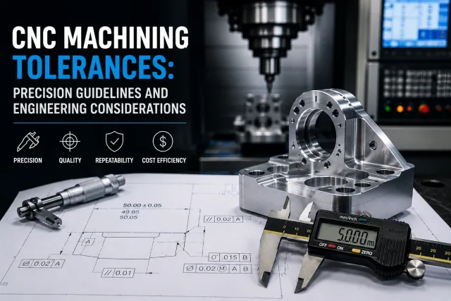
Tolerances are not just numbers on a drawing: they determine whether a part assembles correctly, how much it costs to manufacture, how repeatable the process will be, and how much time inspection requires.
In CNC machining, tolerances connect design, manufacturing, and metrology. A tolerance that is too open can cause vibration, misalignment, or fit problems; an unnecessarily tight tolerance increases cycle time, setups, inspection, and cost without adding real functional value.
From prototypes through production, defining correct tolerances is one of the most important decisions for balancing precision, manufacturability (DFM), and cost.
In this guide we explain what CNC machining tolerances are, how they affect engineering and production, the most common types, industrial standards, cost impact, design best practices, and how to work with a supplier that understands precision and manufacturability.
- What CNC tolerances are — permitted dimensional variation around nominal geometry
- Impact on cost and lead time — greater precision requires more machining and inspection
- General vs critical tolerances — not every dimension needs the same level of accuracy
- Relationship to assembly and performance — they affect fit, repeatability, and functionality
- DFM best practices — how to avoid over-specifying unnecessary dimensions
What are CNC machining tolerances?
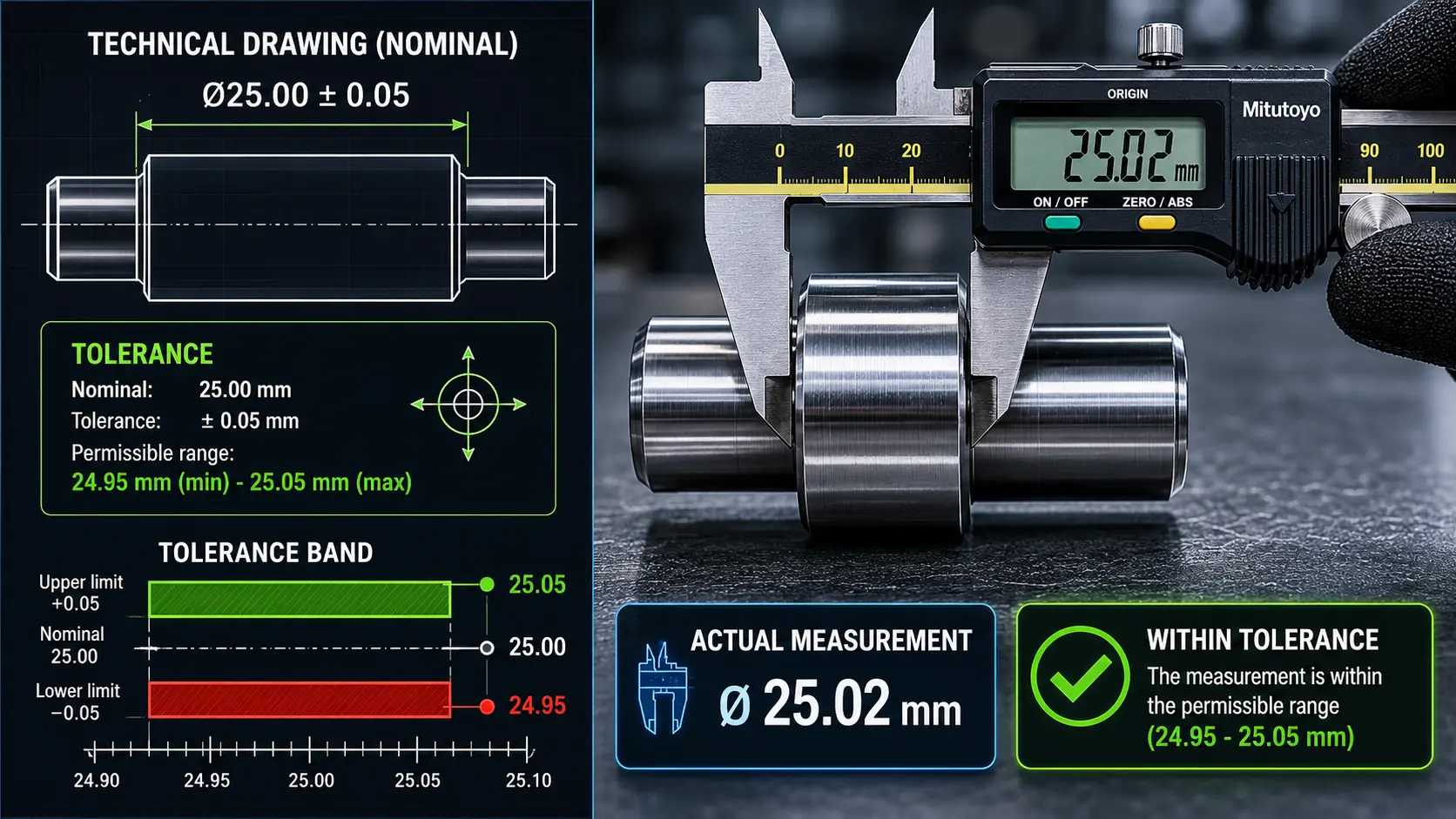
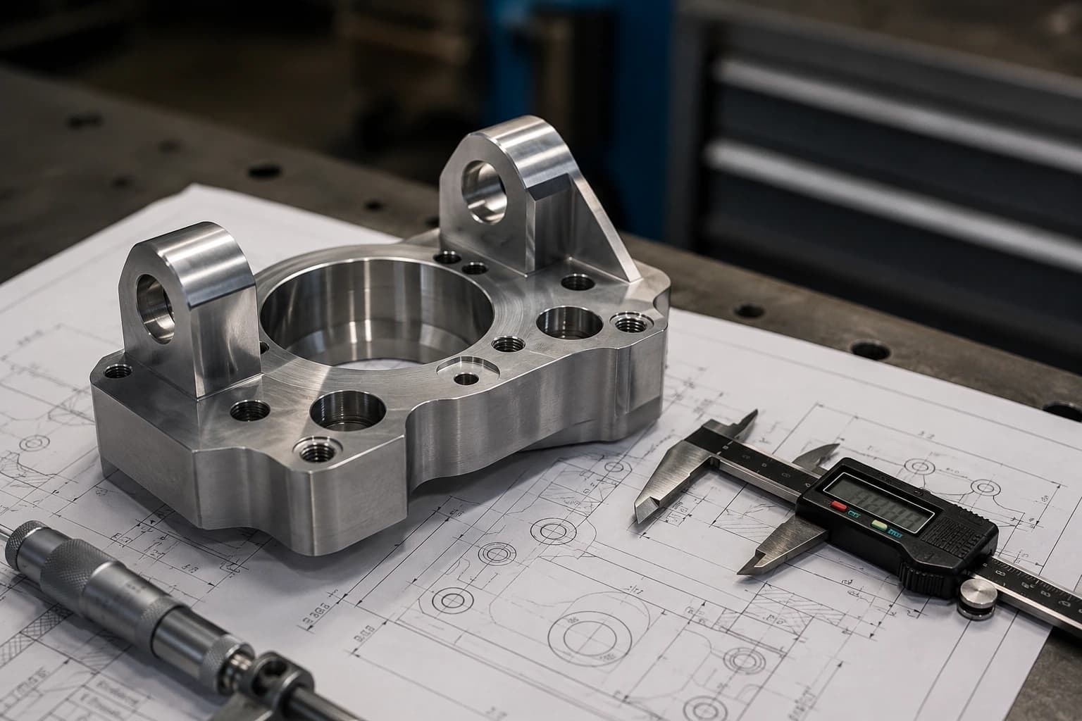
CNC machining tolerances define the acceptable dimensional variation allowed during the manufacture of a part. Instead of producing mathematically perfect dimensions, manufacturing processes generate small variations caused by tooling, material, temperature, vibration, workholding, and measurement.
For example, a nominal dimension of 50.00 mm with a tolerance of ±0.05 mm means any measurement between 49.95 mm and 50.05 mm is considered acceptable.
These controlled variations allow functional components to be manufactured without requiring unnecessary precision that increases cost and production time.
Why no part is perfectly exact
Even on high-precision CNC machining centers, multiple factors generate dimensional deviations during the manufacturing process:
• tool wear
• thermal expansion
• material deflection
• vibration
• spindle concentricity
• part workholding
• toolpath strategy
• measurement variation
That is why tolerances are fundamental: they establish how much error is functionally acceptable so a part can assemble, operate, and be inspected correctly.
As tolerances become tighter, the process requires greater control: more conservative speeds, higher-precision tools, finishing strategies, thermal compensation, and more advanced metrology.
For this reason, tolerances directly impact:
• machining cost
• cycle time
• inspection time
• scrap and rework
• production repeatability
• manufacturing complexity
The most important distinction for engineering is between general tolerances and critical tolerances.
General tolerances apply to the entire part unless otherwise indicated and normally follow standards such as ISO 2768. Critical tolerances, on the other hand, control dimensions related to assembly, concentricity, alignment, interference, sealing, or mechanical motion.
Correctly defining which dimensions are truly critical helps reduce cost, simplify inspection, and improve manufacturability without compromising component performance.
What are CNC machining tolerances?
Nominal dimensions and permitted variation
The nominal dimension represents the theoretical value defined in design, while the tolerance establishes the acceptable dimensional variation around that geometry.
On a technical drawing or in a CAD model with PMI, the manufacturer needs to know both: which dimension must be produced and how much deviation is functionally acceptable for the part to still be considered conforming.
Why variation exists in manufacturing
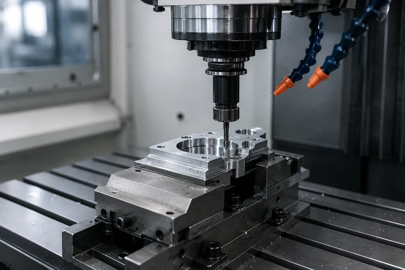
Every manufacturing operation generates small dimensional variations. In CNC machining, factors such as tool wear, material deflection, vibration, workholding, temperature, and toolpath strategy affect the final result.
Although modern CNC processes offer high repeatability and precision, no operation completely eliminates variation. That is why tolerances are fundamental for defining which deviation remains functionally acceptable.
Why no part is perfectly exact
Even on high-precision machining centers, final geometry depends on multiple mechanical and thermal variables. In addition, every measurement contains some level of uncertainty.
For this reason, industry works with conformity limits rather than absolute precision. Tolerances allow functionality, manufacturability, repeatability, and inspection to be balanced without requiring unnecessary precision that increases cost and production time.
On prototypes, a general tolerance may be sufficient; on critical assembly, sealing, or transmission components, a single dimension out of specification can compromise the entire part.
Why are tolerances important in engineering?
- Assembly and fit — they control clearances, interferences, and alignment between components
- Functional performance — they affect sealing, vibration, wear, and load transmission
- Production repeatability — they ensure consistency between prototypes and manufacturing lots
- Quality and inspection — they establish clear acceptance and rejection criteria
- Cost and manufacturability — unnecessarily tight tolerances increase machining and inspection time
Over-tolerancing parts “for safety” is one of the most common mistakes in product development. In many cases, excessively tight tolerances increase CNC machining cost, inspection complexity, and cycle time without actually improving functionality.
Conversely, tolerances that are too open can cause loose assemblies, misalignment, noise, leaks, or premature wear that only appear at advanced validation or production stages.
Types of tolerances in CNC machining
Linear tolerances
Linear tolerances control dimensions such as lengths, diameters, thicknesses, and depths. They are the most widely used on components manufactured through CNC milling and CNC turning, since they define the acceptable dimensional range for critical part features.
These tolerances directly affect assembly, fit, repeatability, and dimensional inspection.
Angular tolerances
Angular tolerances control the permitted deviation between faces, surfaces, or inclined axes. They are common on chamfers, inclined components, tools, brackets, and geometries machined on multiple axes.
Maintaining angular precision requires stable setups, good machine alignment, and in many cases inspection using CMM or angular measurement instruments.
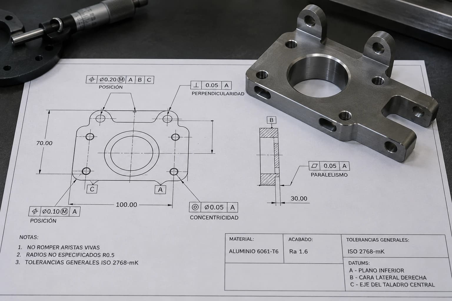
Geometric tolerances (GD&T)
GD&T (Geometric Dimensioning and Tolerancing) uses standardized symbols to control form, orientation, location, and runout of geometric features.
Unlike traditional dimensional tolerances, GD&T communicates how a geometry must behave relative to datum references, allowing functional requirements to be defined more precisely and consistently.
This system is widely used in industries such as aerospace, automotive, medical devices, and precision manufacturing.
Position, concentricity, and perpendicularity tolerances
Geometric tolerances are often applied to critical assembly and alignment features.
Position controls the exact location of holes, slots, or patterns relative to defined datums. Concentricity controls alignment between coaxial diameters, while perpendicularity ensures that surfaces or axes maintain the correct angle relative to a reference.
These tolerances are especially important on housings, shafts, adapters, mounting interfaces, and transmission components.
Surface finish tolerances
Surface finish tolerances control the final texture of a machined part and are normally specified using parameters such as Ra or Rz.
Surface finish impacts friction, sealing, wear, fatigue, and aesthetic appearance. Finer surfaces generally require finishing tools, more conservative cutting parameters, or additional secondary processes.
In industrial applications, selecting the correct finish helps balance functionality, cost, and manufacturing time.
See also our industrial finishes guide compatible with metals and engineering plastics.
Standard tolerances in CNC machining
General tolerances used in industry
When a drawing does not specify individual tolerances for each dimension, general tolerances defined through notes on the drawing or industrial standards are normally applied.
These tolerances allow functional parts to be manufactured without overloading the design with unnecessary specifications, simplifying manufacturing, inspection, and communication between engineering and the supplier.
In many CNC machining projects, general tolerances are sufficient for non-critical features that do not affect assembly, alignment, or functional performance.
ISO 2768 and equivalent standards
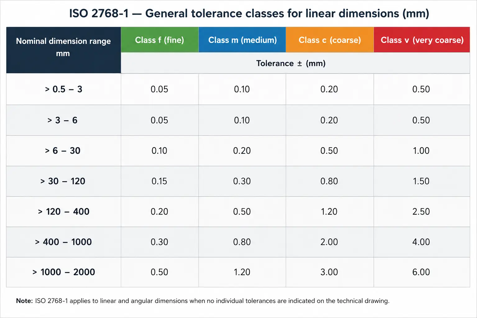
ISO 2768 is one of the most widely used standards for general tolerances on machined parts. It defines different precision classes for linear and angular dimensions when no specific tolerance is indicated on the drawing.
The most common classes include:
• fine (f)
• medium (m)
• coarse (c)
• very coarse (v)
On prototypes, general production, and standard industrial components, ISO 2768-m (medium) is usually a reasonable starting point because it balances precision, manufacturability, and cost.
Applying tighter tolerances only where they are truly necessary helps reduce machining time, inspection complexity, and scrap risk.
| Class | Typical application | Relative precision level |
|---|---|---|
| f (fine) | Precision components and critical interfaces | High precision |
| m (medium) | General use in CNC machining | Balanced precision |
| c (coarse) | Non-critical industrial parts | Moderate precision |
| v (very coarse) | Roughing geometries or low criticality | Wide variation bands |
Typical capabilities in CNC milling and turning
Tolerance capabilities depend on multiple factors such as machine, material, tool, geometry, aspect ratio, workholding, and machining strategy.
In CNC milling, many shops maintain relatively tight tolerances on critical features while using general tolerances on non-functional surfaces.
In CNC turning, internal and external diameters usually offer high repeatability, although long, thin, or eccentric parts may require additional support to control deflection and vibration.
Ultra-precision capabilities require greater thermal stability, finishing tools, advanced inspection, and more controlled processes, so they normally increase cost and production time.
It is important to understand that a tolerance considered “standard” depends on project context. A simple structural part does not require the same level of precision as a sealing component, a linear motion system, or a critical assembly interface.
For this reason, a good design practice is to apply tight tolerances only on important functional features and maintain general tolerances on the rest of the geometry.
How tolerances impact CNC machining cost
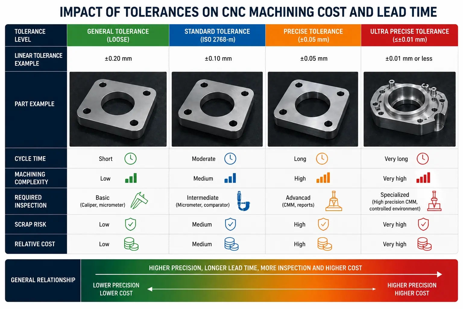
Tolerances have a direct impact on cost, production time, and inspection. As a part requires greater precision, the manufacturing process needs more control, more machine time, and more conservative machining strategies.
In many projects, an unnecessarily tight tolerance can significantly increase cost without actually improving part functionality.
- Greater precision — requires more finishing passes, higher-quality tools, and more controlled cutting speeds
- Longer cycle time — conservative feeds and parameters help reduce vibration, deflection, and heat buildup
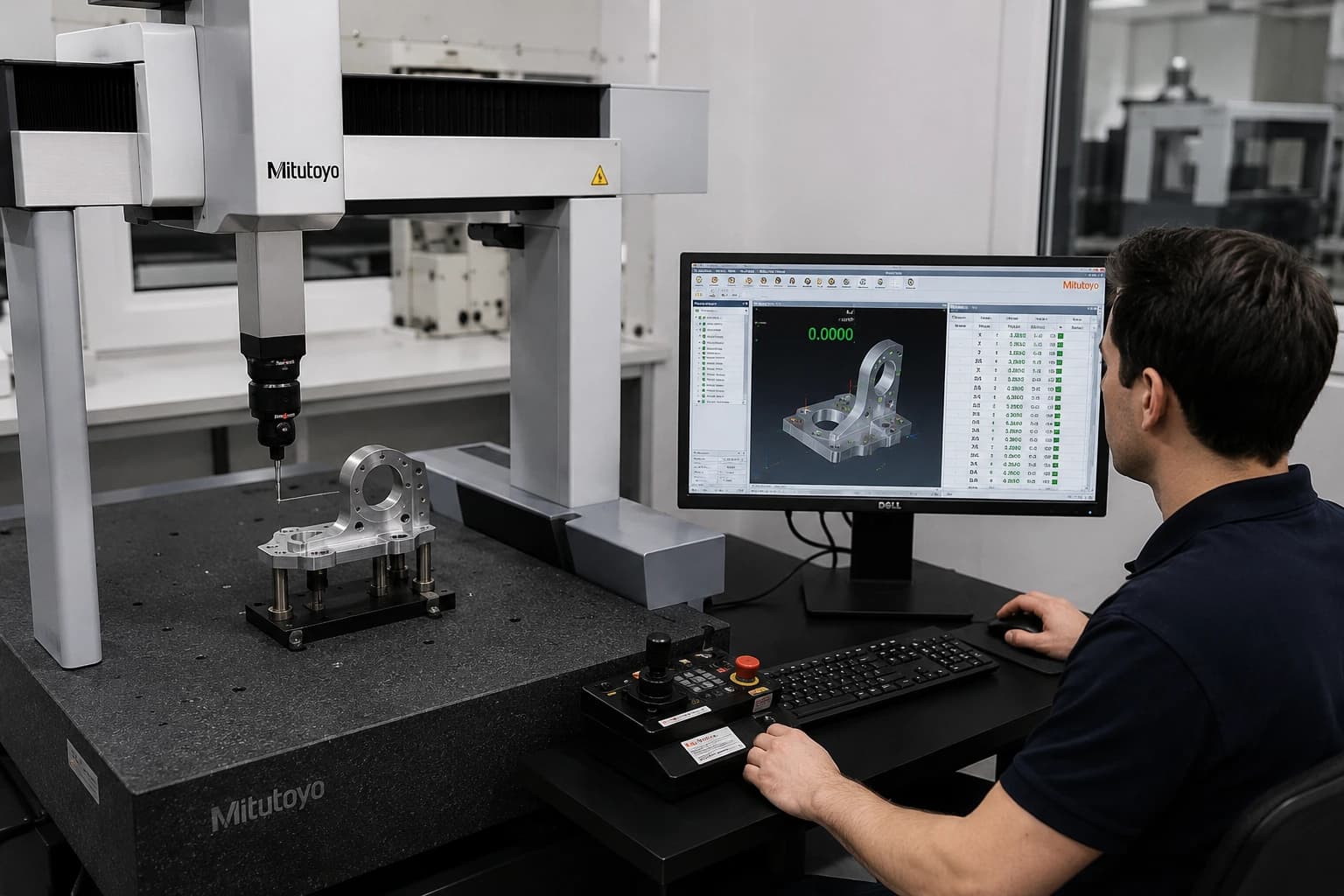
- Additional inspection — critical tolerances often require micrometers, CMM, and more detailed dimensional reports
- Higher scrap and rework risk — difficult-to-maintain tolerances increase nonconforming parts
- More setup complexity — workholding, alignment, and thermal compensation become more critical
- Machine capability — ultra-precision tolerances require more advanced equipment, tooling, and processes
One of the most common mistakes in product development is applying very tight tolerances across the entire geometry even though only a few dimensions are truly functional.
In practice, many surfaces can remain under general tolerances while only critical assembly, sealing, alignment, or motion features require greater precision.
When it makes sense to relax tolerances
If a dimension does not directly affect assembly, mechanical performance, or functionality, it normally does not need extremely strict tolerances.
On prototypes, general industrial parts, and non-critical components, standards such as ISO 2768 usually offer a reasonable balance between precision, manufacturability, and cost.
Reducing unnecessary tolerances helps decrease machining time, simplify inspection, and improve production performance without compromising component quality.
Before specifying high-precision tolerances across the entire part, it is worth identifying which dimensions truly control component function.
That approach allows manufacturability to be optimized, cost to be reduced, and precision to be maintained only where it adds real value.
For a broader view on pricing, processes, and manufacturing factors, see also our guide on CNC machining cost.
Design guidelines for CNC tolerances
Defining tolerances correctly not only improves precision: it also reduces cost, simplifies inspection, and facilitates manufacturing.
In many projects, a well-thought-out tolerance strategy has more impact on production time and repeatability than increasing machine capability or requiring more complex processes.
- Apply precision only where it adds value — functional and assembly dimensions require greater control; the rest can remain under general tolerances
- Design for manufacturability (DFM) — radii, depths, and access compatible with standard tools reduce machining complexity
- Avoid tolerance stack-up — long dimensional chains can create fit problems in assemblies
- Define clear datums — especially on drawings with GD&T, since the inspection reference must align with the manufacturing setup
- Balance precision and cost — prototypes and first iterations normally do not require ultra-strict production tolerances
- Simplify inspection — dimensions that are easy to measure reduce metrology time and interpretation risk
One of the best engineering practices is to tighten tolerances only after validating which features truly impact the product’s functional performance.
That approach helps accelerate iterations, reduce rework, and keep manufacturing costs more efficient during development and production scaling.
Beyond tolerances, a clean, well-organized CAD package accelerates quoting, DFM review, and CAM programming.
If you are preparing files for manufacturing, see also our CAD file to CNC machining guide, where we explain recommended formats, technical documentation, and best practices for sending parts to production.
GD&T in CNC machining
GD&T (Geometric Dimensioning and Tolerancing) allows geometry, orientation, and functional location of part features to be controlled using standardized symbols.
Unlike traditional linear tolerances, GD&T defines how a geometry must behave relative to datum references that represent the real assembly condition.
This allows functional requirements to be communicated more clearly between design, manufacturing, and inspection.
In precision applications, GD&T helps control hole patterns, alignment between axes, concentricity, complex profiles, and critical surfaces without needing to over-tolerance every individual dimension.
It also facilitates more consistent inspection and improves repeatability across different lots and suppliers.
Advantages of GD&T in manufacturing and inspection
- Clearer technical communication — reduces ambiguity between engineering, CAM, and metrology
- Functional assembly control — tolerances relate directly to part function
- Less over-tolerancing — avoids applying unnecessary precision across the entire geometry
- Greater repeatability — improves consistency between setups, lots, and inspection processes
- Compatibility with CMM and advanced metrology — facilitates automated dimensional validation
Common GD&T symbols in CNC machining
- Position — controls location of holes, slots, and axes relative to datums
- Perpendicularity and parallelism — control orientation between surfaces or geometries
- Circularity and concentricity — used on rotational components and coaxial diameters
- Surface profile — defines permitted deviation on complex geometries and 3D contours
- Runout — controls dynamic variation on rotational components
For GD&T to work correctly, the inspection method must align with how the part will be fixtured and used in assembly.
If the datums defined on the drawing do not represent the real manufacturing or mounting condition, the part may “pass inspection” and still cause functional problems in application.
Materials and their relationship to tolerances
The ability to maintain tolerances depends not only on the machine or process, but also on material behavior during machining.
Factors such as hardness, thermal stability, internal stress, expansion, deflection, and heat generation directly affect dimensional precision, surface finish, and repeatability.
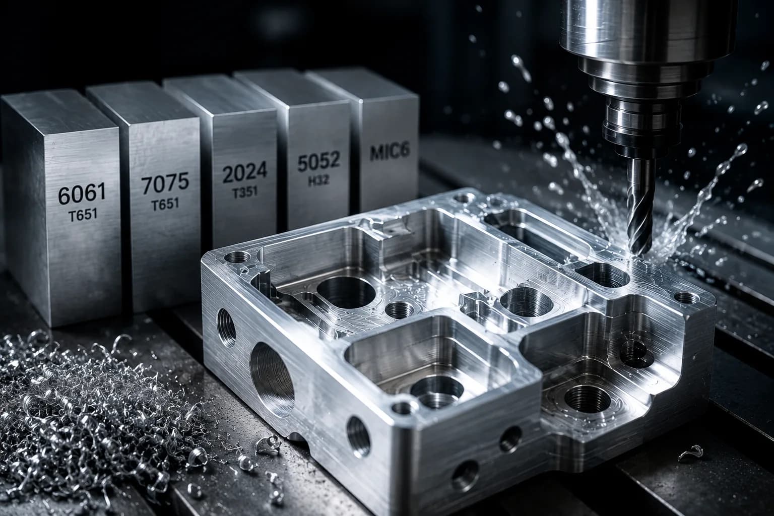
Aluminum
Aluminum 6061-T6 and Aluminum 7075-T6 offer excellent machinability and good dimensional stability in most industrial applications.
Thanks to their mechanical properties and ease of cutting, they are widely used in precision prototypes, fixtures, structural components, and production parts.
They also allow high cutting speeds and good surface finish with less tool wear compared with more abrasive or harder materials.
Steels
1018 Steel, 4140 Steel, and 304 Stainless Steel usually require more conservative machining parameters due to higher cutting forces and heat generation.
In particular, 304 stainless steel can show greater tendency toward work hardening and vibration, making it more demanding to maintain tight tolerances and consistent finishes.
On long or thin-walled parts, controlling deflection and stability during the process becomes especially important.
Titanium and engineering plastics
Titanium Grade 5 and other high-strength alloys generate more heat during machining and usually require more controlled cutting strategies to maintain dimensional precision and tool life.
In materials such as Acetal, Nylon, and PEEK, factors such as thermal expansion, material relaxation, and moisture absorption can affect critical dimensions over time.
For this reason, tolerances used on metal components are not always appropriate for engineering plastics.
Selecting realistic tolerances according to material behavior helps improve manufacturability, reduce scrap, and avoid dimensional problems during assembly or functional validation.
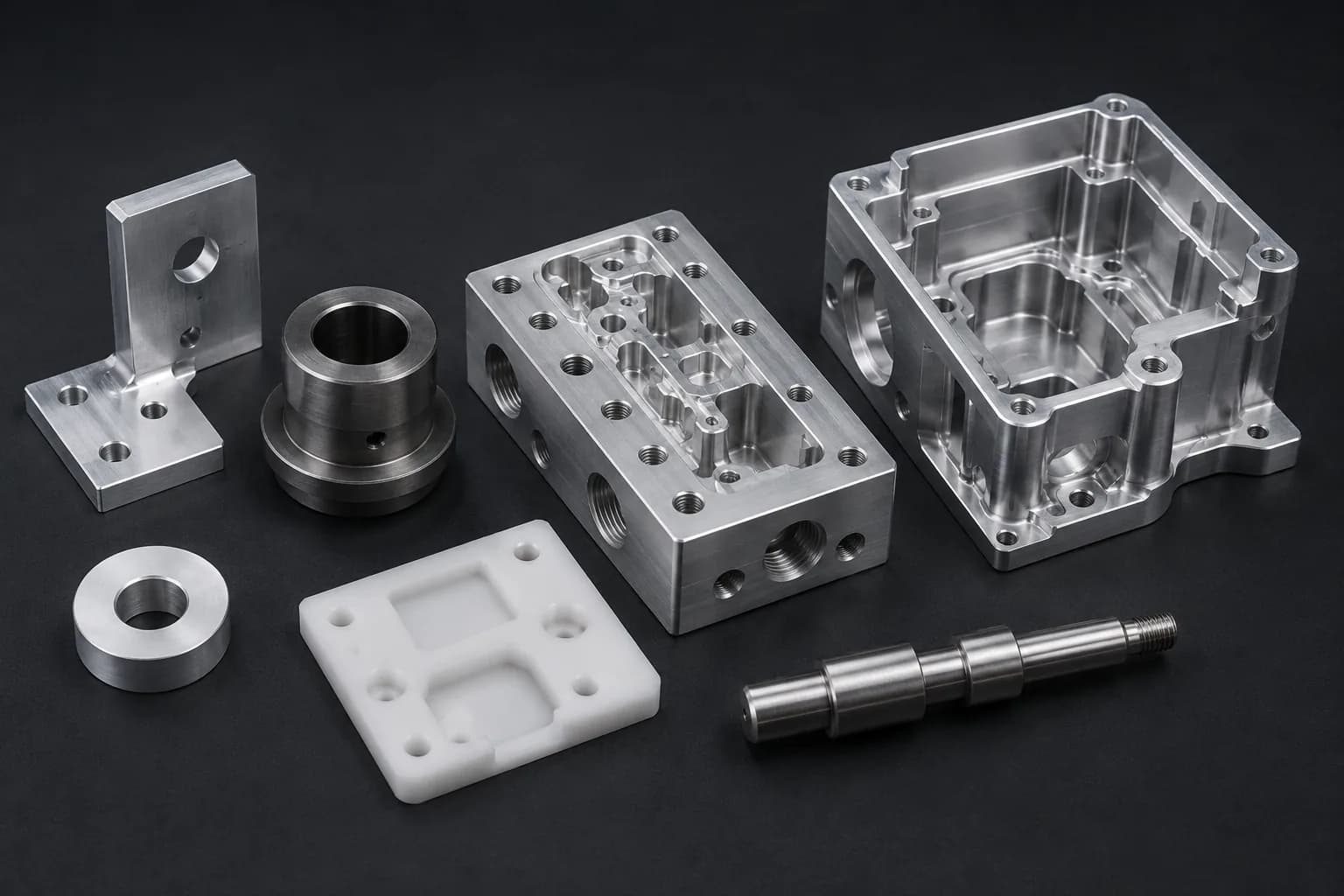
CNC processes and precision capabilities
Each CNC process has distinct capabilities in terms of geometry, repeatability, concentricity, and dimensional control.
Choosing the correct process depends on factors such as part complexity, length-to-diameter ratio, production volume, number of setups, and tolerance requirements.
- CNC milling — ideal for cavities, flat surfaces, prismatic geometries, and complex components
- CNC turning — optimized for diameters, concentricity, and rotational components
- Swiss-type machining — excellent for small, long, high-precision parts
- CNC mill-turn machining — combines milling and turning operations, reducing setups and error accumulation
- Grinding and secondary processes — used when tighter dimensional tolerances or surface finishes are required
Reducing setup changes, controlling workholding, and correctly selecting the manufacturing strategy are key factors for improving repeatability and maintaining critical tolerances consistently.
Inspection methods for CNC tolerances
Dimensional inspection is a fundamental part of quality control in CNC machining. As tolerances become tighter, measurement, validation, and documentation complexity also increases.
Selecting the correct inspection method depends on factors such as geometry, production volume, functional criticality, and traceability requirements.
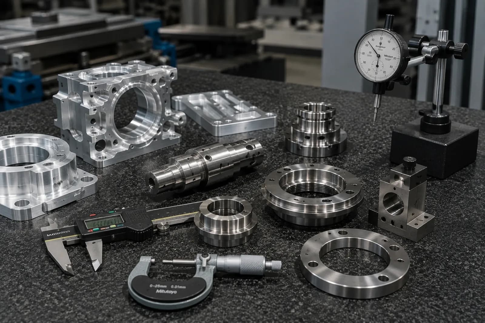
- Calipers and micrometers — used for quick inspection of diameters, thicknesses, and general dimensions
- Coordinate measuring machines (CMM) — allow complex 3D geometry to be validated and detailed dimensional reports to be generated
- Optical comparators — useful for profiles, contours, and two-dimensional geometry in repetitive production
- Gage pins and thread gages — verify holes, internal diameters, and threaded features using functional limits
- Surface finish instruments — used to validate parameters such as roughness and surface texture
- Dimensional reports and traceability — documentation required for audits, process validation, and critical projects
On precision components, the inspection strategy should be considered from the design and quoting stage.
A drawing with multiple geometric tolerances, advanced GD&T, or extensive documentation requirements can significantly increase metrology and validation time, even on relatively small parts.
The relationship between inspection, cost, and production time
In many projects, inspection time can represent a significant portion of total manufacturing cost.
Critical features often require additional inspection, specific CMM setups, complete dimensional reports, and manual validation by quality.
For this reason, defining realistic tolerances and limiting advanced inspection only to important functional dimensions helps maintain a better balance between precision, lead time, and cost.
Common mistakes when specifying tolerances
Defining tolerances incorrectly can increase cost, complicate manufacturing, and create assembly problems even when parts are dimensionally conforming.
Many production problems do not come from CNC process capability, but from ambiguous drawings, unnecessarily tight tolerances, or lack of alignment between design, manufacturing, and inspection.
- Over-tolerancing the entire geometry — applying extremely tight tolerances across the whole part without real functional need
- Creating ambiguous drawings — contradictory notes, redundant dimensions, or lack of clear datum references
- Sending incomplete documentation — STEP models without PDF or without identifying critical assembly dimensions
- Ignoring surface finish requirements — specifying roughness without defining important functional zones
- Not considering tolerance stack-up — multiple small variations can create impossible assemblies
- Defining tolerances incompatible with the process — some geometries require grinding, honing, or secondary processes
- Not aligning inspection with real function — parts that pass metrology but fail in assembly or application
A good tolerance strategy must consider functionality, manufacturability, inspection method, and real production process behavior.
In many cases, simplifying tolerances improves repeatability, reduces machining time, and accelerates engineering iterations.
How to choose the correct tolerances for your project
Ideal tolerances depend on part type, application, production volume, and the level of precision truly required.
Not all projects need the same dimensional approach: a functional prototype, a cosmetic part, and a critical automation component have completely different priorities.
| Project context | Recommended approach | Primary objective |
|---|---|---|
| Prototypes | General tolerances with control on critical dimensions | Reduce cost and accelerate iterations |
| Low-volume production | Greater control on functionally validated features | Improve repeatability and assembly |
| Cosmetic components | Priority on surface finish and visual appearance | Aesthetic consistency |
| Critical industrial applications | GD&T, advanced inspection, and strict dimensional control | Precision and functional reliability |
In many projects, the best balance between cost, precision, and lead time is achieved when engineering and manufacturing collaborate from early design stages.
Performing DFM review before releasing production helps identify unnecessary tolerances, simplify geometries, and reduce inspection or rework risks.
For fast production strategies and lead time optimization, see also our guide on fast CNC machining.
How PREMSA Industries supports precision projects
At PREMSA Industries we review CAD files, technical drawings, and dimensional requirements to align tolerances with real manufacturing processes.
We work on CNC machining projects for prototypes, low-volume production, and industrial components using processes such as CNC milling, CNC turning, mill-turn, and Swiss-type machining.
- Quoting with DFM review — analysis of critical tolerances and manufacturability before production
- Support for precision parts — evaluation based on geometry, material, and inspection method
- Prototypes and low volume — functional validation before scaling production
- Clear technical communication — alignment between engineering, manufacturing, and inspection
- Dimensional and inspection support — documentation and validation for industrial projects
Request a CNC quote with DFM review by sending your STEP file and technical drawing. You can also contact our team for projects with critical dimensional requirements or special tolerances.
Frequently asked questions about CNC machining tolerances
Answers on dimensional precision, GD&T, inspection, materials, and manufacturability in CNC machining projects.
- What is a standard tolerance for CNC machining?
- In many industrial projects, general tolerances based on standards such as ISO 2768 are used when the drawing does not specify each dimension individually. For functional or assembly features, tolerances are usually defined specifically according to geometry, material, and component requirements.
- How precise can CNC machining be?
- Achievable precision depends on factors such as machine, material, geometry, workholding, tooling, and inspection. Modern CNC processes can maintain very tight tolerances in specific applications, although higher precision levels normally increase machining time, inspection, and cost.
- When does it make sense to use GD&T?
- GD&T is especially useful when part function depends on the relationship between holes, axes, surfaces, or complex geometries. This system helps communicate functional requirements more clearly between engineering, manufacturing, and inspection.
- Do tighter tolerances increase cost?
- Yes. Tighter tolerances require more controlled machining strategies, higher-precision tools, additional inspection, and more production time. Applying strict tolerances only where they truly add functional value helps optimize cost and manufacturability.
- Which materials are harder to hold in tolerance?
- Materials with high heat generation, tendency toward vibration, or thermal expansion are usually more demanding dimensionally. Some titanium alloys, stainless steels, and many engineering plastics require special strategies to maintain precision and dimensional stability.
- Do I need to send a PDF in addition to the STEP file?
- Yes, it is highly recommended. The STEP file conveys geometry, while the PDF includes tolerances, surface finishes, critical notes, and inspection requirements that may not be clearly defined in the CAD model.
- Is dimensional inspection part of the CNC process?
- Yes. Dimensional inspection is a fundamental part of quality control in CNC manufacturing. Depending on the project, calipers, micrometers, CMM, thread gages, and dimensional reports may be used to validate critical features.
- How can I reduce cost without compromising quality?
- One of the best strategies is to apply strict tolerances only on important functional dimensions and maintain general tolerances on the rest of the part. It also helps to simplify geometries, reduce setups, and perform DFM review before production.
In many industrial projects, general tolerances based on standards such as ISO 2768 are used when the drawing does not specify each dimension individually. For functional or assembly features, tolerances are usually defined specifically according to geometry, material, and component requirements.
Achievable precision depends on factors such as machine, material, geometry, workholding, tooling, and inspection. Modern CNC processes can maintain very tight tolerances in specific applications, although higher precision levels normally increase machining time, inspection, and cost.
GD&T is especially useful when part function depends on the relationship between holes, axes, surfaces, or complex geometries. This system helps communicate functional requirements more clearly between engineering, manufacturing, and inspection.
Yes. Tighter tolerances require more controlled machining strategies, higher-precision tools, additional inspection, and more production time. Applying strict tolerances only where they truly add functional value helps optimize cost and manufacturability.
Materials with high heat generation, tendency toward vibration, or thermal expansion are usually more demanding dimensionally. Some titanium alloys, stainless steels, and many engineering plastics require special strategies to maintain precision and dimensional stability.
Yes, it is highly recommended. The STEP file conveys geometry, while the PDF includes tolerances, surface finishes, critical notes, and inspection requirements that may not be clearly defined in the CAD model.
Yes. Dimensional inspection is a fundamental part of quality control in CNC manufacturing. Depending on the project, calipers, micrometers, CMM, thread gages, and dimensional reports may be used to validate critical features.
One of the best strategies is to apply strict tolerances only on important functional dimensions and maintain general tolerances on the rest of the part. It also helps to simplify geometries, reduce setups, and perform DFM review before production.
Conclusion
CNC machining tolerances transform design intent into measurable manufacturing and inspection criteria. Defining them correctly allows precision, functionality, repeatability, and cost to be balanced without adding unnecessary complexity to the production process.
Applying general tolerances where they are sufficient and controlling only critical features helps improve manufacturability, accelerate lead times, and reduce assembly or dimensional validation problems.
Combining good design practices, industrial standards, DFM review, and appropriate inspection processes is one of the most effective ways to move from a CAD model to functional parts ready for production.
At PREMSA Industries we support CNC machining projects for prototypes, low-volume production, and industrial components with a focus on precision, manufacturability, and dimensional inspection.
Request a CNC quote by sending your CAD file and technical drawing. You can also contact PREMSA for projects with critical tolerances or special inspection requirements.
If you are preparing or optimizing designs, see our CNC machining design guide.

Written by
Adrian Cavazos and the PREMSA Engineering Team
Adrian Cavazos, founder of PREMSA Industries, leads a manufacturing engineering team specialized in CNC machining, metal fabrication, and production-ready solutions. The team works closely with customers to optimize designs, improve manufacturability (DFM), and ensure reliable, scalable production from prototypes to volume manufacturing.