Moving from a CAD model to a physical part is not just about having a “finished” design. The quality of the 3D file, clarity of the technical drawing, and information included with your quote request directly affect lead times, cost, manufacturability, and production repeatability.
A clean STEP file with defined material, tolerances, and finishes can speed up engineering review, CAM programming, and production from first contact. By contrast, incomplete models, context-free STL files, or outdated drawings cause delays, extra revisions, and the risk of manufacturing incorrect parts.
In this guide we explain how to prepare files for CNC machining, which formats manufacturing teams actually use, what information speeds up quotes, and how PREMSA Industries reviews CAD models for prototypes and production with online quoting.
Why proper CAD file preparation speeds up quotes and production
In CNC manufacturing, the CAD file is the foundation of nearly the entire production workflow: DFM review, process selection, CAM programming, tool definition, dimensional inspection, and setup planning.
When a supplier receives an incomplete file, an STL mesh without specifications, or a model with no material defined, quoting stops for additional technical questions. That creates email threads, revisions, crossed versions, and lost time before programming even begins.
A properly prepared CAD package lets you evaluate manufacturability from the start, flag complex geometry, validate critical tolerances, and estimate machining time with much greater accuracy. The result is a far more efficient flow between engineering, quoting, and production.
Beyond faster response times, good CAD preparation also reduces manufacturing errors, minimizes rework, and improves repeatability when a project moves from prototype to production.
What information CNC machining suppliers actually need
A 3D model alone rarely contains everything needed to manufacture a part correctly. Engineering and manufacturing teams also need context on function, tolerances, finishes, quantities, and project priorities.
The more complete the technical package from the start, the faster and more accurate the quote. It also helps avoid incorrect assumptions during programming, inspection, and production.
- Solid 3D file in a manufacturable format (preferably STEP or Parasolid).
- Exact material and required condition, including alloy, temper, or heat treatment if applicable.
- Part quantity and project context: prototype, pilot, validation, or repetitive production.
- Critical tolerances and surface finishes only where functionally necessary.
- Threads, inserts, hardware, and special notes clearly documented on the technical drawing or specifications.
- Project priorities: lowest cost, shortest lead time, maximum precision, or future scalability.
- Updated technical drawings with critical dimensions, datums, revisions, and inspection criteria.
- Expected delivery format: individual part, assembly, kit, or packaged production.
In complex industrial projects — especially in sectors such as aerospace and defense, robotics, or electronics and semiconductors — this information can directly impact manufacturing strategy, inspection, and final cost.
That is why preparing the CAD package correctly before requesting a quote not only speeds up timelines: it also improves manufacturability, technical communication, and final part quality.
What is a CAD file for CNC manufacturing?
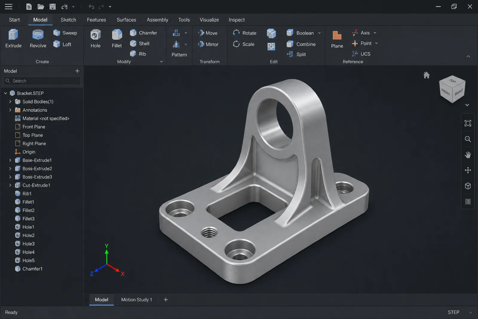
A CAD file for manufacturing is the digital model — and, when applicable, the technical drawing — that defines geometry, dimensions, tolerances, and functional requirements before a part is fabricated. In CNC machining, these files are used to review manufacturability, generate CAM toolpaths, plan setups, and program tools.
Beyond “showing the part,” a well-prepared CAD file allows engineering to understand design intent, select the right processes, and reduce uncertainty during quoting and production. That is why file quality directly impacts response time, cost, and repeatability.
Difference between 3D models and technical drawings
The 3D model defines volume, surfaces, geometric relationships, and the general shape of the part. The technical drawing (PDF, DWG, or equivalent) communicates critical information that normally does not exist within the solid: tolerances, surface finishes, datums, threads, chamfers, material notes, inspection criteria, and special requirements.
In real manufacturing, both work together. The solid enables programming and fabrication; the technical drawing defines which features are critical and how the part should be validated.
The ideal is to send STEP + updated drawing. When only one of the two is sent, the supplier must assume default values or interpret design intent, which increases the risk of errors, revisions, and quoting delays.
How CAD files are used in the manufacturing workflow
- DFM review: detect difficult geometries, deep cavities, impossible radii, or unrealistic tolerances before programming production.
- Process selection: determine whether the part is better suited for CNC milling, CNC turning, sheet metal fabrication, 3D printing, or hybrid processes.
- CAM programming: generate toolpaths, cutting strategies, speeds, and machining operations from the 3D solid.
- Production planning: define material, tools, fixturing, setups, dimensional inspection, and sequence of operations.
- Inspection and quality: validate critical dimensions, tolerances, and functional criteria defined on the technical drawing.
- Scalability to production: reuse geometry and processes to move from prototype to repeatable production with greater consistency.
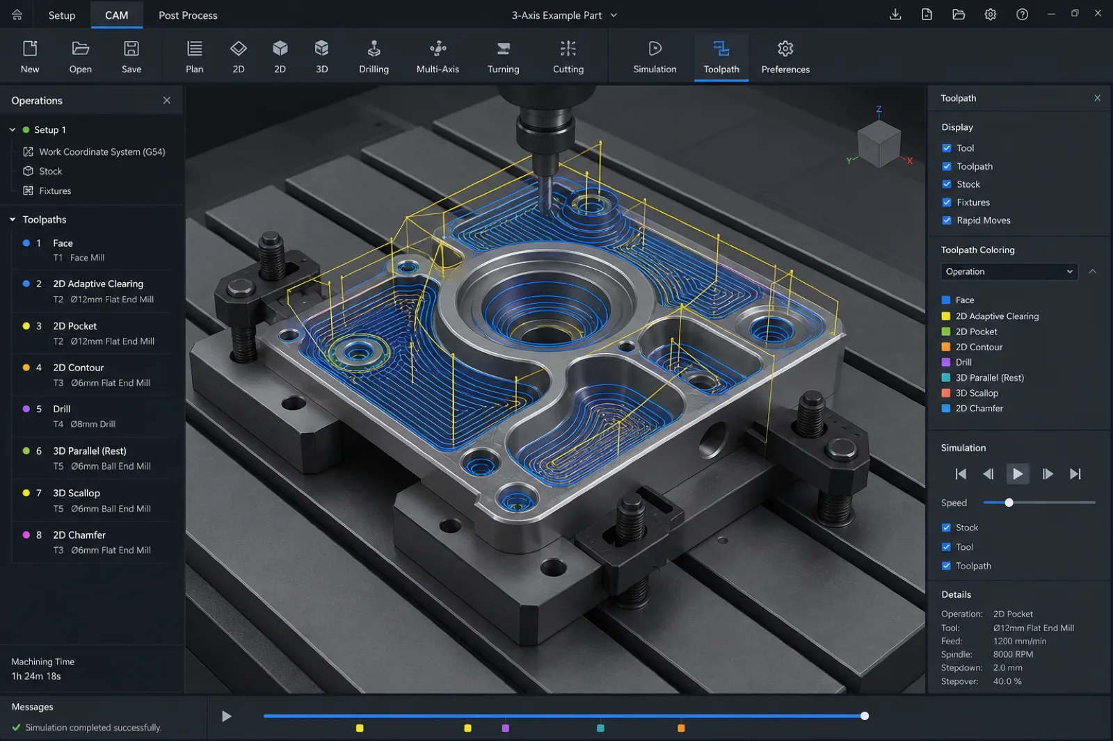
From digital model to CNC toolpath
CAM software does not “guess” design intent or automatically interpret which dimensions are critical. The system simply reads geometry, surfaces, radii, depths, and parameters defined within the CAD file.
That is why a clean solid in STEP or Parasolid format — with correct units, closed geometry, and no import errors — is essential to generate reliable toolpaths, cutting strategies, and repeatable machining sequences.
During CAM programming, the CAD model becomes real manufacturing operations: tool selection, cutting speeds, roughing strategies, finishing, drilling, threading, and multiple fixturing setups. Any issue in the original file can translate into rework, programming errors, or additional engineering time.
This is especially important in processes such as CNC milling, CNC turning, and multi-axis manufacturing, where model accuracy directly impacts surface quality, tolerances, and production repeatability.
Most Common File Formats for CNC Machining
Not all CAD formats work the same way in CNC manufacturing. Some preserve exact solid geometry and integrate easily with CAM software; others are designed for triangulated meshes, legacy exchange, or specific 2D profiles.
Choosing the correct format can reduce import errors, speed up DFM review, and facilitate tool programming. In industrial production environments, this directly impacts quoting times, repeatability, and final part quality.
The following table summarizes the formats most used in quoting and manufacturing, and when each one is appropriate.
| Format | Extension | Primary use | PREMSA recommendation |
|---|---|---|---|
| STEP | .STEP / .STP | Solid exchange between CAD, CAM, and manufacturing | Preferred format for CNC quoting and programming |
| Parasolid | .X_T / .X_B | High-compatibility solid geometry between CAD systems | Excellent for precision machining |
| SolidWorks | .SLDPRT | Native parametric design file | Accepted; we also recommend exporting a STEP file |
| IGES | .IGS / .IGES | Legacy surface-based exchange format | Use only if STEP is not available |
| DXF | .DXF | 2D profiles for sheet cutting and fabrication | Ideal for sheet cutting |
| STL | .STL | Triangular mesh used mainly in 3D printing | Not recommended as the only file for CNC |
STEP files (.STEP / .STP)
STEP (ISO 10303) is the most widely used standard format for sharing 3D models between CAD, CAM, and manufacturing engineering software. Its main advantage is that it preserves precise solid geometry and complex mathematical relationships with much higher fidelity than legacy or mesh-based formats.
In CNC manufacturing, STEP is normally the preferred format for quoting, DFM review, and CAM programming because it reduces import problems and facilitates interoperability between different systems.
Whether the model comes from SolidWorks, Fusion 360, Inventor, CATIA, or Siemens NX, exporting a clean STEP allows manufacturing teams to open, review, and program the part with less technical friction.
Why STEP is the most widely used standard in manufacturing
- Preserves solid, precise geometry, not only surfaces or triangulated meshes.
- Has broad compatibility across CAD, CAM, inspection, and industrial manufacturing software.
- Reduces import errors, gaps, and corrupt surfaces compared with legacy formats.
- Facilitates DFM review, CAM programming, and faster quotes.
- Enables work across different CAD platforms without depending on specific software versions.
- Ideal for processes like CNC Milling, CNC Turning and Multiaxis Machining.
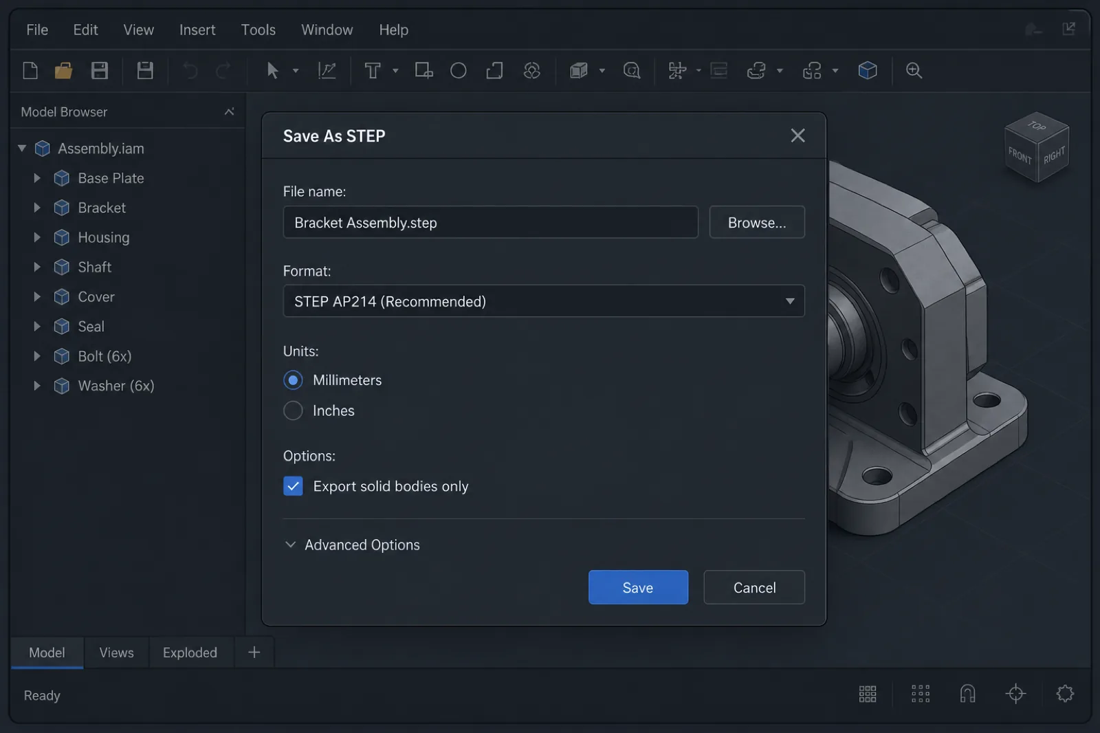
How to export STEP correctly
Exporting a STEP file seems like a simple step, but in CNC manufacturing it is one of the most common causes of quoting delays, import problems, and lost time in technical review.
A poorly exported STEP can contain open surfaces, geometry errors, incorrect units, or unnecessary information that forces the supplier to repair the file before CAM programming begins. In some cases, it can even produce incorrectly scaled parts or geometries that cannot be machined.
If you search for terms like *“export STEP for CNC”*, *“Fusion 360 export STEP”*, or *“SolidWorks export STEP machining”*, the issue is usually not STEP itself, but how it was exported from CAD.
Preparing the export correctly before sending it speeds up DFM review, improves CAD/CAM interoperability, and reduces friction during quoting and production.
| Step | What to do | Why it matters |
|---|---|---|
| Units | Confirm mm vs inches before exporting | Avoid parts scaled incorrectly by a 25.4× factor |
| Solids only | Export closed solid bodies, not surfaces only | CAM software needs solid volume to program |
| Clean the model | Hide sketches, planes, and unnecessary geometry | Reduce noise and possible import conflicts |
| Validate geometry | Use check/heal/repair tools before sending | Prevents gaps, open faces, and import errors |
| Name revisions clearly | Use clear names such as `part_revB.step` | Improves traceability and document control |
| Verify export | Open the STEP in another viewer or CAM software | Confirm the file was exported correctly |
Units: millimeters vs inches
Defining units correctly before export is one of the most important steps when preparing files for CNC manufacturing. An error between millimeters and inches can cause incorrectly scaled parts, wrong quotes, or even complete production out of specification.
Although many CAD systems detect units automatically, you should never assume the file will be interpreted correctly when imported into another CAM software or manufacturing environment.
If you design in inches but the supplier interprets the model in millimeters — or vice versa — the part can import 25.4 times larger or smaller. That is why, in addition to checking units in CAD, it is recommended to state them explicitly on the technical drawing, in engineering notes, or during online quoting.
| Issue | Consequence | How to avoid it |
|---|---|---|
| Model exported in inches | The part is interpreted in mm and appears 25.4× smaller | Confirm units before exporting STEP |
| Drawing and CAD in different units | Inconsistent dimensions during manufacturing | Keep the same system in 3D and 2D |
| Missing unit notes | Incorrect assumptions in production | State mm or inches on drawing and RFQ |
| Incorrect automatic import | Incorrect scaling in CAM | Validate dimensions when opening the STEP |
Healing geometry and solid validation
Before sending a file for manufacturing, it is recommended to validate that the solid is fully closed and free of geometric errors. Small corrupt faces, gaps between surfaces, or invalid intersections can cause problems when importing the model into CAM.
Tools such as *Import Diagnostics* in SolidWorks, *Repair* functions in Fusion 360, or built-in validators in CAM software help detect defective geometry before production.
Correcting these issues directly in CAD is much faster and more economical than discovering them during programming, inspection, or machining.
| Issue | Impact on manufacturing | Recommendation |
|---|---|---|
| Open surfaces | CAM does not recognize a valid solid | Repair and close geometry before export |
| Corrupt small faces | Errors in toolpaths and surfaces | Use geometry healing tools |
| Invalid intersections | Failures during CAM programming | Validate complex bodies before sending |
| Duplicate bodies | Confusion in manufacturing or quoting | Clean assemblies before export |
Suppress sketches and export solids only
Files intended for manufacturing should contain only the information needed to fabricate the part. Sketches, construction planes, auxiliary axes, and reference geometry usually add noise when importing the model into CAM software.
When possible, export one part per STEP file and avoid including unnecessary components within complex assemblies. If the project requires multiple parts, clearly identify which components should be quoted or manufactured.
Keeping files clean also facilitates DFM review, programming, and document traceability during production.
- SolidWorks: File → Save As → STEP; export selected bodies only when applicable.
- Fusion 360: Save As → STEP; validate units in Document Settings before export.
- Inventor / CATIA / Creo / NX: export AP214 or AP242 when available and confirm a valid solid after import.
- Complex assemblies: separate individual parts when the supplier does not need the full assembly for manufacturing.
- Document control: use clear names such as `housing_revC.step` or `bracket_assembly_revB.step`.
What CAD software customers use for CNC machining
In modern CNC manufacturing, files can come from virtually any professional CAD platform. From startups developing rapid prototypes to aerospace companies with complex assemblies, what matters is not the specific software you use, but the quality of the file exported for manufacturing.
At PREMSA Industries we receive models from multiple industrial CAD ecosystems and typically work through STEP files to ensure compatibility between design, engineering, and CAM programming.
You do not need to change software to quote CNC parts. What matters is exporting a clean STEP, validating geometry, and accompanying the model with clear information on material, tolerances, and finishes.
These are some of the platforms most commonly used by teams working with *SolidWorks machining*, *Fusion 360 CNC*, industrial mechanical design, and manufacturing in Mexico.
| Software | Typical profile | Manufacturing tip |
|---|---|---|
| SolidWorks | Mechanical design, fixtures, automation, and assembly parts | Export STEP AP214/AP242; send SLDPRT only when requested |
| Fusion 360 | Startups, rapid prototypes, and integrated CAD/CAM workflows | Excellent for rapid iteration; validate units before STEP export |
| Autodesk Inventor | Industrial machinery, tooling, and mechanical equipment | Keep revisions clear in file name and drawing |
| CATIA | Aerospace, automotive, and complex surfaces | Accompany STEP with technical drawing and critical CTQs |
| Creo (PTC) | Industrial products and large assemblies | Export individual parts when a full assembly is not required |
| Siemens NX | Advanced manufacturing, molds, and complex tooling | Excellent CAD/CAM integration; STEP remains the universal standard |
| Onshape | Collaborative teams and cloud-based development | Verify correct revision before sharing links or exports |
| Rhino / Grasshopper | Complex design, organic surfaces, and special geometries | Validate closed solids before exporting STEP for CNC |
Although each platform uses different modeling and export tools, the manufacturing flow usually converges on universal formats such as STEP or Parasolid for CAM programming, DFM review, and inspection.
In complex industrial projects, especially in sectors such as aerospace and defense, hardware, or robotics, maintaining revision control and traceability between CAD, drawing, and production is as important as the 3D model itself.
If you design in Fusion 360 for CNC or export from SolidWorks for machining, the most efficient flow is usually the same: validated model → STEP export → technical drawing → manufacturing specifications → quote.
CAD software is only the design tool. What the manufacturing supplier really needs is clear, manufacturable information: correct solid geometry, material, tolerances, finishes, revisions, and project context.
A well-prepared model reduces engineering time, speeds up CAM programming, and avoids multiple iterations during quoting and production.
Parasolid files (.X_T / .X_B)
Parasolid is one of the most widely used geometric kernels within industrial CAD/CAM software. The `.X_T` (text) and `.X_B` (binary) formats preserve high-quality solid geometry and usually integrate very well in CNC manufacturing workflows.
In many cases, Parasolid imports even cleaner than other neutral formats, especially on complex parts, advanced surfaces, or industrial assemblies.
For precision processes such as CNC milling, CNC turning, and multi-axis manufacturing, Parasolid is an excellent alternative when STEP is not available.
SolidWorks files (.SLDPRT)
`.SLDPRT` files are SolidWorks’ native format and are extremely common in mechanical manufacturing, industrial automation, fixtures, and assembly design.
Although many shops can open native SolidWorks files, exporting a parallel STEP remains the most recommended practice for manufacturing. This avoids version incompatibilities, reduces dependence on the original software, and facilitates integration with different CAM systems.
In addition, sending STEP together with a technical drawing usually speeds up DFM review and quoting, especially when multiple teams participate in engineering and production.
IGES files (.IGS / .IGES)
IGES was for many years one of the standard formats for CAD exchange, especially in complex surfaces and legacy engineering workflows. However, compared with STEP or Parasolid, it usually causes more import and geometry problems.
IGES files can contain open surfaces, gaps, disconnected faces, or invalid solids after importing into CAM. That is why IGES is currently recommended only when STEP is not available.
If you work with IGES, it is important to validate the solid after import and confirm that geometry is fully closed before programming or quoting begins.
DXF files for sheet cutting and fabrication
DXF is one of the most widely used formats for 2D geometry within cutting and metal fabrication processes. Instead of describing complete 3D solids, DXF defines profiles, contours, holes, and planar paths.
It is the typical format for sheet metal fabrication, sheet cutting, laser cutting, waterjet, and other processes where thickness and the 2D profile define the part.
When working with DXF, it is important to clean duplicate geometry, unnecessary splines, and open lines before sending the file for manufacturing.
STL files and when they are NOT ideal for CNC
STL represents geometry through a triangular mesh rather than as a true parametric solid. This format is excellent for 3D printing and visualization, but it has important limitations within CNC manufacturing.
In processes such as milling or turning, working only with STL usually forces reconstruction of geometry, surface approximation, or redoing critical features before CAM programming. That increases engineering time, dimensional risk, and manufacturing cost.
The more complex the part, the more problematic it can become to rely solely on an STL mesh.
If your workflow is oriented toward printed prototypes, STL works perfectly for additive manufacturing. But for machined parts in aluminum, steel, titanium, or engineering plastics, STEP remains the most recommended option for CNC manufacturing.
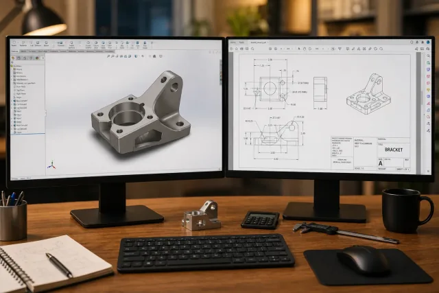
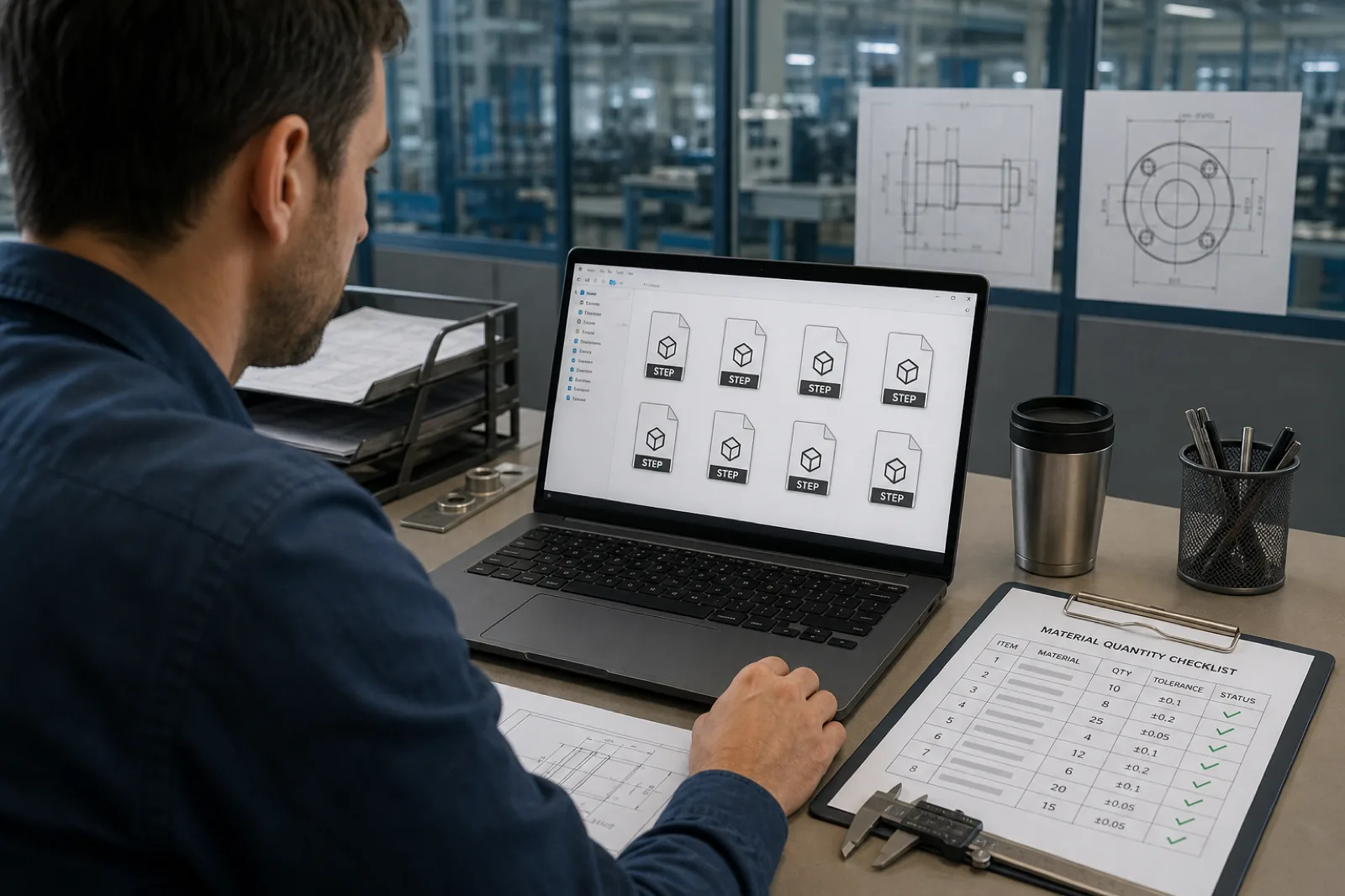
Visual references: CAD, drawing, CAM, and documentation quality
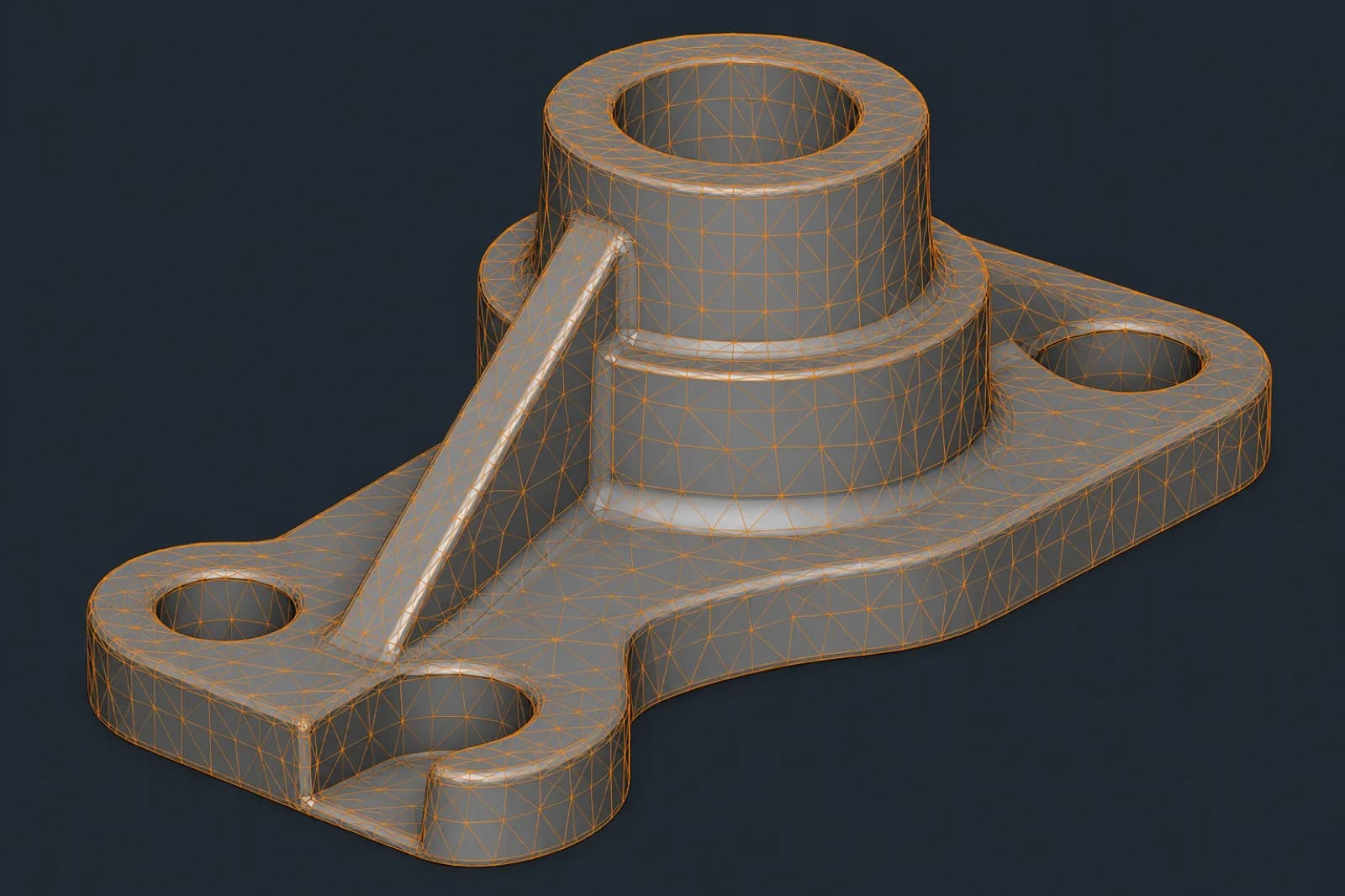
Preparing files for CNC manufacturing is not fully understood through theory alone. Visually comparing a clean STEP solid, a triangulated STL mesh, a correctly dimensioned technical drawing, and a CAM toolpath helps you understand how engineering and manufacturing actually interpret a project.
In industrial production, the visual quality of documentation also communicates the level of technical preparation. An organized CAD package conveys clarity, reduces ambiguity, and speeds up DFM review, quoting, and programming.
That is why this type of article works best with real examples: well-prepared solid models, drawings with clear CTQs, correct STEP exports, and CAM toolpath references.
| Element | What it communicates | Impact on manufacturing |
|---|---|---|
| STEP model | Solid geometry and real part volume | Foundation for CAM programming and manufacturing |
| STL mesh | Shape approximated through triangles | Useful for 3D printing, limited for CNC |
| Technical drawing | Tolerances, CTQs, threads, and finishes | Define inspection and acceptance criteria |
| CAM toolpath | Cutting strategies and tool movements | Determines machining time and setups |
| CAD assembly | Functional relationship between components | Helps validate interferences and context |
| Revision-controlled drawing | Document control and traceability | Reduces risk of manufacturing wrong revisions |
In complex projects, especially in sectors such as automotive, hardware, and manufacturing, documentation quality can directly impact quoting time, dimensional accuracy, and production repeatability.
The clearer and more organized the CAD package, the less time is lost interpreting design intent and the faster the project can move toward manufacturing.
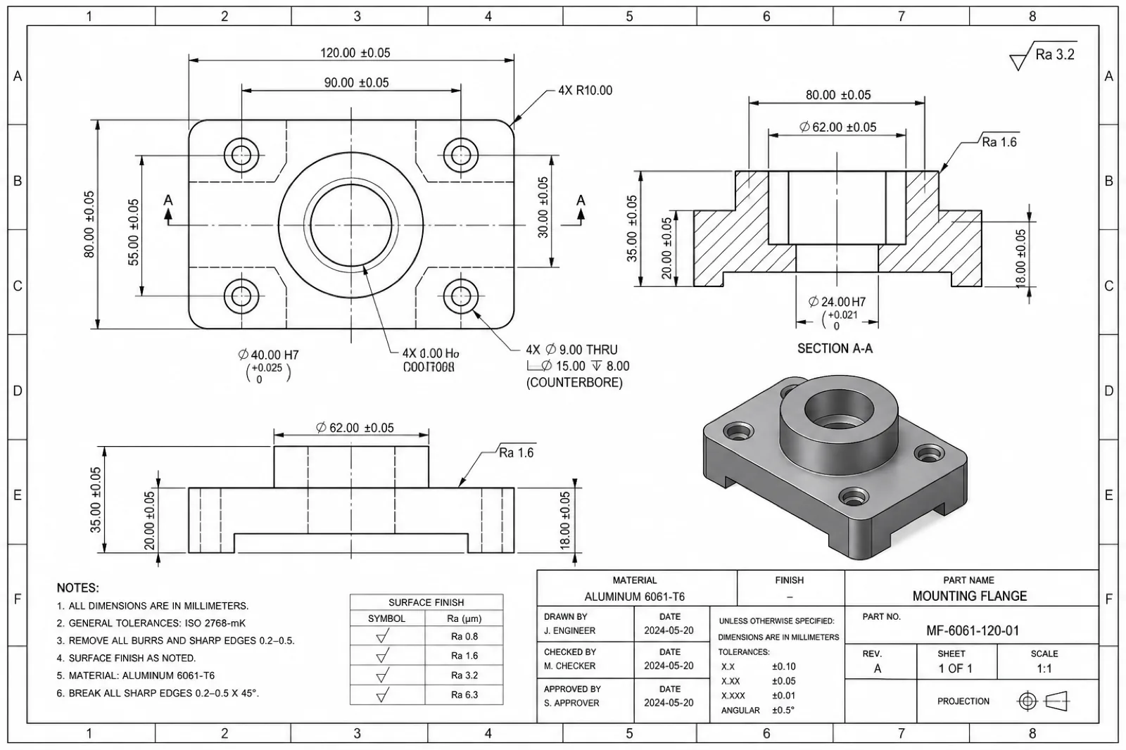
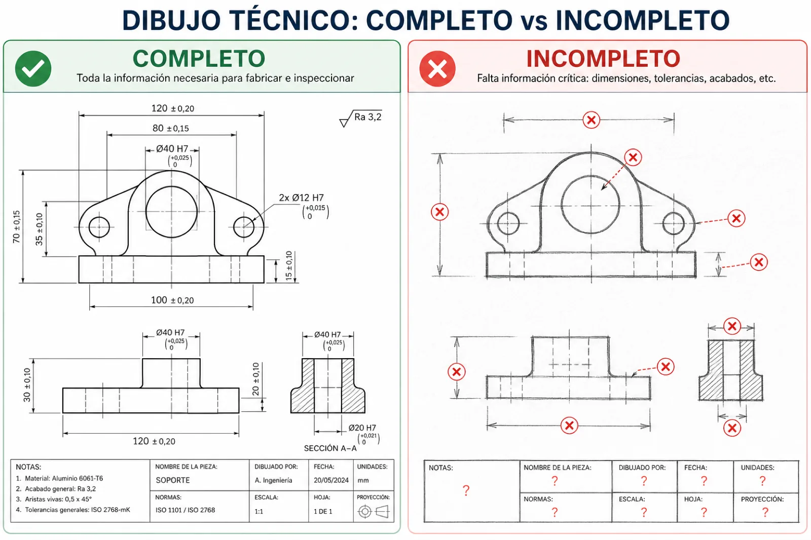
| Aspect | Good drawing | Incomplete drawing |
|---|---|---|
| Material | Clearly defined alloy (e.g., Aluminum 6061-T6, 304 SS, PEEK) | Material missing, ambiguous, or “TBD” |
| Tolerances | Identified CTQs + general tolerance such as ISO 2768 | No tolerances or the entire drawing at unnecessary ±0.01 |
| Finishes | Ra, anodizing, paint, or process defined on functional faces | Ambiguous notes such as “fine finish” or “commercial finish” |
| Threads | Standard, depth, and complete callout (e.g., M6×1.0-6H) | Hole or circle only without specification |
| Review | STEP, PDF, and BOM match the same revision | 3D model and drawing belong to different revisions |
| Units | mm or inches clearly stated | Unit system not specified |
| Datums / referencias | Functional datums and defined inspection references | No clear references for dimensional inspection |
| Critical dimensions | Clearly identified functional features | The shop must assume which dimensions are important |
| Manufacturing notes | Treatments, inserts, hardware, and special requirements defined | Information distributed in emails or not documented |
| Visual clarity | Clean, organized, readable drawing | Cluttered, disorganized, or with duplicate dimensions |
STEP vs STL: Which Should You Send for CNC Machining?
Although both formats represent 3D geometry, STEP and STL are designed for completely different workflows. Understanding this difference is key to avoiding manufacturing problems, quoting delays, and errors during CAM programming.
In CNC manufacturing, the correct format can directly impact dimensional accuracy, surface quality, engineering time, and final production cost.
While STEP preserves precise, editable solid geometry, STL represents the part through an approximate triangulated mesh. That makes STEP the standard for CNC programming and STL a better option for 3D printing or visualization.
| Criterion | STEP (solid) | STL (mesh) |
|---|---|---|
| Geometry type | Precise B-Rep solid with mathematical surfaces | Approximate triangulated mesh |
| Geometric precision | High precision for manufacturing and inspection | Depends on triangulation density |
| CAM programming | Direct, stable, and manufacturable | Limited or requires reconstruction |
| Editing in CAD | Editable features and partially preserved parametrics | Difficult to edit or modify |
| Tolerances | Compatible with drawings and CTQs | Difficult to infer from the mesh |
| File size | Optimized for complex solids | Can grow very large at high resolution |
| Best application | CNC, production, functional prototypes, and industrial manufacturing | 3D printing, rendering, and visualization |
| CAM compatibility | Excellent in industrial manufacturing | Varies by software and complexity |
| Risk of errors | Lower if the solid is validated | Higher risk of defective or inaccurate surfaces |
| PREMSA recommendation | Always send for CNC quoting | Use only as reference or supplement |
Differences between solid geometry and triangulated mesh
A STEP file preserves exact mathematical surfaces, real radii, and precise solid geometry. This allows CAD/CAM software to correctly interpret cavities, features, tolerances, and toolpaths.
By contrast, STL represents the part through thousands of flat triangles that approximate the original shape. The coarser the triangulation, the less accurate the geometry; the finer it is, the heavier and more complex the file becomes.
Although both may look similar visually, for CNC manufacturing the difference is enormous: STEP describes design intent; STL only approximates appearance.
Common issues when using STL for manufacturing
- Curved surfaces converted into visible triangular facets.
- More engineering time to reconstruct manufacturable geometry.
- Difficulty editing parametric features easily.
- Hard to identify tolerances and functional dimensions.
- Import problems in industrial CAM software.
- Risk of conservative or more expensive quotes due to geometric uncertainty.
- Extremely heavy files when STL resolution is very high.
When STL can still be useful
Although STL is not ideal as the primary format for CNC, it remains extremely useful in certain workflows.
It is appropriate for 3D printing, rapid visual validation, conceptual review, and some hybrid processes where it is used together with STEP and technical drawings.
It can also serve as a visual reference during design review or dimensional comparison after manufacturing.
If the main objective is additive manufacturing, STL works perfectly. But for machined parts in aluminum, stainless steel, titanium, or engineering plastics, STEP remains the most recommended format for professional CNC manufacturing.
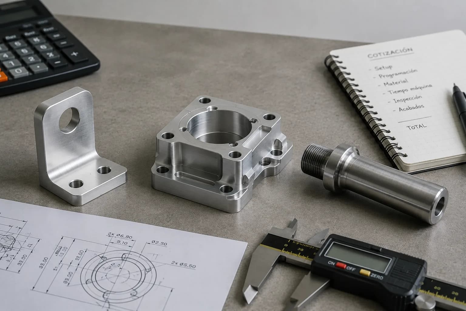
What a CNC Machining Quote Should Include
An accurate quote does not depend solely on the 3D file. In CNC manufacturing, the technical context of the project is just as important as geometry.
Material, quantity, tolerances, finishes, lead time, and functional requirements directly affect manufacturing strategy, tool selection, programming times, and final cost.
The more complete the technical package from the first submission, the faster and more accurate the quote will be. It also reduces revisions, additional emails, and the risk of manufacturing incorrect parts.
Engineering and production teams normally need this information before DFM review and CAM programming begin.
| Element | Why it matters | Example / note |
|---|---|---|
| Material | Defines manufacturability, cost, tooling, and lead time | Aluminum 6061-T6, 304 SS, Titanium Grade 5, PEEK |
| Cantidad | Affects per-part economics and setup strategy | 1 prototype, 25 pilot, 1000 production |
| Finishes | Adds secondary processes and additional inspection | Anodized, bead blast, Ra 3.2 µm, powder coat |
| Tolerances | They determine machining time and inspection | ISO 2768-m, ±0.01 mm on CTQs |
| Threads / inserts | They require tools, sequence, and validation | M6×1.0, helicoils, PEM inserts |
| Lead time | Prioritizes capacity and production sequence | Rush, standard, or scheduled production |
| Technical drawing | Define CTQs and acceptance criteria | Updated PDF with notes and revisions |
| Project review | Avoid manufacturing incorrect versions | Rev A, Rev B, updated ECO |
| Functional application | Helps prioritize precision or cost | Fixture, critical assembly, housing, prototype |
| Empaque / entrega | Can affect logistics and protection | Individual parts, kits, or assembly |
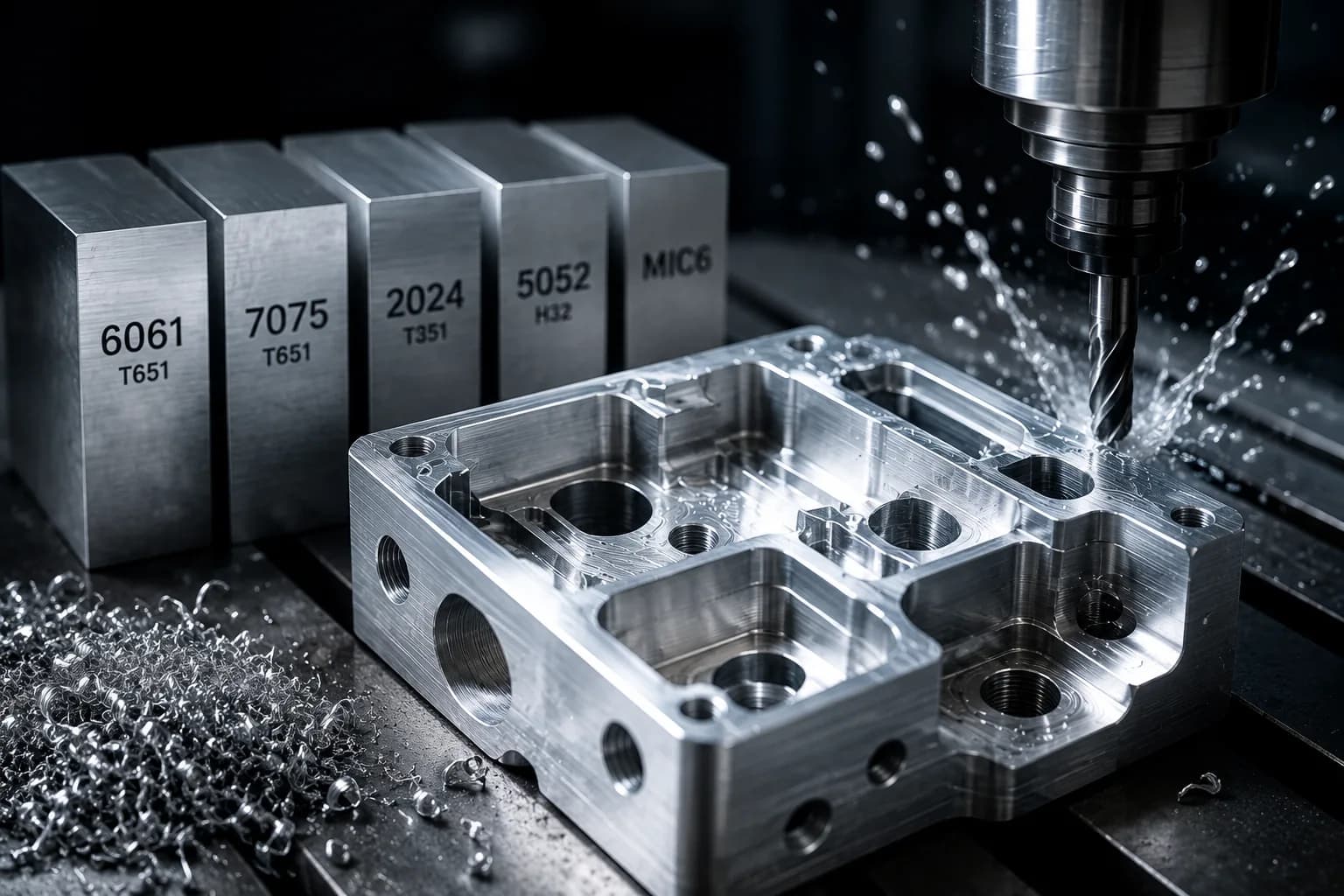
Required material
Material affects practically every aspect of manufacturing: machinability, cutting speed, tools, surface finish, inspection, and final cost.
That is why it is important to specify alloy, condition, and any required treatment from the start.
Quoting aluminum 6061 is not the same as quoting Grade 5 titanium, nor is machining 304 stainless steel the same as PEEK or ULTEM.
If material is not defined, the supplier must assume default values — and the quote can change significantly when the actual material is confirmed.
You can explore options in our material library.
Part quantity
Quantity completely defines the manufacturing strategy.
A single prototype part usually prioritizes flexibility and speed. Repetitive lots, by contrast, allow optimization of programming, tools, fixturing, and cycle times.
Higher quantities also help amortize setups, initial inspection, and CAM programming, reducing unit cost.
That is why it is important to indicate whether the project is a prototype, pilot, recurring production, or design validation.
Surface finishes
Surface finishes can affect appearance, corrosion resistance, friction, conductivity, and functional performance of the part.
Processes such as anodizing, bead blasting, passivation, painting, or electropolishing usually add secondary operations, additional time, and specific inspection.
It is also important to indicate which faces truly require critical finish and which can remain at standard machining finish.
Also see our industrial finishes compatible with aluminum, stainless steel, titanium, and engineering plastics.
Critical tolerances
Not every dimension requires extremely tight tolerances.
In CNC manufacturing, unnecessarily tolerancing the entire part increases machining time, inspection complexity, and final cost.
The ideal is to apply strict tolerances only on functional features such as fits, alignments, seals, bearings, or critical interfaces.
For the rest of the geometry, general standards such as ISO 2768 are usually sufficient and much more efficient from a manufacturing standpoint.
Threads, inserts, and special features
Threads, inserts, press-fit hardware, and special features must be clearly documented on the technical drawing or requirements list.
It is important to specify standard, depth, fit class, and any associated functional requirement.
These characteristics usually require specific tools, additional operations, and critical inspection during production.
On sheet metal parts or industrial assemblies, it also helps to indicate whether PEM inserts, helicoils, heat-set inserts, or other fastening systems will be used.
Expected lead time
Expected lead time helps prioritize capacity, production sequence, and material availability.
An urgent project may require different manufacturing strategies compared with a flexible or scheduled order.
Indicating from the start whether the priority is speed, cost, or precision helps align expectations between engineering, production, and purchasing.
Technical drawings and engineering notes
The technical drawing remains one of the most important documents in CNC manufacturing.
That is where CTQs, tolerances, finishes, datums, inspection notes, revisions, and functional requirements that normally do not exist within the 3D model are defined.
The PDF must match exactly the revision of the STEP sent and stay updated throughout the quoting and production flow.
The clearer and more organized the technical documentation, the less time is lost interpreting design intent and the faster the project can move toward manufacturing.
What tolerances are actually necessary
One of the factors that most impacts cost, machining time, and inspection in CNC machining is usually not the material: it is poorly defined tolerances.
Applying extremely tight tolerances to the entire part — for example ±0.02 mm or ±0.05 mm globally — can significantly increase cycle time, programming complexity, dimensional inspection, and production scrap without delivering real functional value.
In industrial manufacturing, the key is not “make everything ultra precise”; the key is to apply precision only where assembly or function truly requires it.
To optimize quoting, manufacturability, and repeatability, it usually helps to think about dimensions in three levels: general tolerances, functional tolerances, and critical characteristics (CTQ).
| Level | When to use it | Typical example |
|---|---|---|
| General (ISO 2768-m/k) | Non-critical dimensions and general geometry | External contours, part bodies, cosmetic features |
| Funcional | Mechanical interfaces and alignments | H7/g6 fits, bearing or bushing location |
| CTQ | Critical features for performance or assembly | Flatness, concentricity, sealing, or critical interfaces |
| Cosmetic | Visible surfaces but not functional | Visual finish or surface aesthetics |
| Repetitive production | Parts that must assemble consistently | Repeatable datums and locating features |
The tighter the tolerance, the more complex the manufacturing process becomes. Depending on geometry, this can require special tools, slower cutting strategies, grinding, thermal control, or additional dimensional inspection.
In many cases, excessive tolerance ends up raising cost without truly improving functional performance of the part.
- Do not tolerance what is not measured in assembly: if a face is cosmetic, finish usually matters more than an extreme tolerance.
- Relate tolerance to real function: a bearing hole requires more control than a decorative exterior face.
- Align tolerance with process: turning usually controls diameters better than milling on thin walls or flexible parts.
- Define clear datums: they help avoid error stack-up and improve dimensional inspection.
- Avoid global tight tolerances: unnecessarily tolerancing the entire drawing increases cost quickly.
- Consider the material: aluminum, titanium, stainless steel, and plastics behave differently during machining.
- Connect tolerance to cost: each additional decimal can mean more cycle time, more inspection, and lower throughput.
| Tolerance | Typical impact | Cost impact |
|---|---|---|
| ±0.5 mm | Standard fast manufacturing | Low cost |
| ±0.1 mm | Moderate dimensional control | Normal production cost |
| ±0.02 mm | Greater process control and inspection | Notable increase in time and cost |
| ±0.005 mm | Advanced processes, thermal control, or grinding | Very high cost and slower production |
If you are optimizing budget or looking to reduce lead time, tolerances are one of the first places where engineering and manufacturing can generate major improvements.
You can also read our article on CNC machining cost, where we explain how tolerances, materials, and geometric complexity affect final production price.
How to Prepare a 3D Model for CNC Manufacturing
Design for manufacturability (DFM) means creating parts with not only how they should look in mind, but how they will actually be fabricated.
In CNC machining, every geometry interacts with real tools: end mills, drills, inserts, toolholders, vises, and fixturing systems. Ignoring these limitations can increase cost, programming time, and the risk of errors during production.
A model optimized for manufacturing usually reduces setups, simplifies CAM programming, improves repeatability, and speeds up quoting.
These principles help you prepare more manufacturable and efficient 3D models for CNC production.
| Concept | Common issue | DFM recommendation |
|---|---|---|
| Tool access | Deep or inaccessible cavities | Design geometries reachable with standard tools |
| Internal radii | Perfectly square internal corners | Use radii compatible with tool diameter |
| Wall thicknesses | Very thin or flexible walls | Maintain manufacturable thicknesses by material |
| Setups | Parts that require multiple re-clampings | Reduce orientations and fixture changes |
| Tolerances | Entire model with extreme precision | Apply tight tolerances only on CTQs |
| Fixturing and datums | Lack of references for fixturing or inspection | Design stable surfaces and clear references |
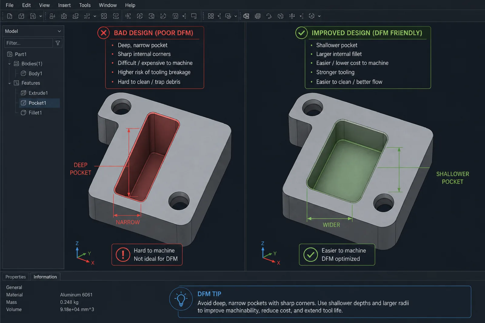
| Cavity depth | Excessive depth-to-diameter ratio | Avoid pockets that are too deep and narrow |
| Small threads | Threads difficult to machine or inspect | Use standard sizes when possible |
Often, small changes in the CAD model can produce enormous reductions in machining time and production cost.
For example, slightly increasing an internal radius, simplifying a deep cavity, or reducing unnecessary tolerances can allow stiffer tools, fewer setups, and much more efficient CAM toolpaths.
- Avoid impossible-to-machine geometries: closed cavities, undercuts without strategy, or features inaccessible to standard tools.
- Design adequate internal radii: end mills have real diameter; perfectly square corners usually require EDM or secondary processes.
- Maintain manufacturable wall thicknesses: walls that are too thin can vibrate, deform, or break during cutting.
- Consider tool accessibility: minimize setups and allow stable tool approach.
- Avoid unnecessarily strict tolerances: tolerance only functional features and CTQs.
- Design for fixturing and workholding: include stable surfaces, references, and clear datums for manufacturing and inspection.
- Reduce extreme pocket depth: deep cavities increase tool deflection and cycle time.
- Use standard drill and thread sizes: simplifies tools, inspection, and availability.
In sectors such as industrial automation, robotics, and hardware, applying DFM principles from CAD can greatly accelerate the transition from prototype to production.
The more manufacturable the design from the start, the faster the project can move toward CAM programming, quoting, and repeatable fabrication.
How to reduce cost from CAD
A large share of CNC part cost is defined long before the machine starts cutting material.
Complex geometries, excessive tolerances, deep cavities, or unnecessary setups usually increase programming time, tool wear, inspection, and scrap risk.
The good news is that many of these decisions can be optimized directly from CAD, before submitting the quote.
Changing a digital model often takes minutes; correcting problems after programming, manufacturing, or inspection can cost hours or even days.
Applying DFM principles from design helps reduce cost, accelerate production, and improve repeatability in both prototypes and repetitive manufacturing.
| Practice | Why it increases cost if ignored | DFM alternative |
|---|---|---|
| Avoid deep pockets | Long tools generate vibration and slow cycles | Keep depth less than 3–4× tool diameter |
| Avoid tiny internal radii | Requires micro end mills, EDM, or special tooling | Use radii compatible with standard tools |
| Avoid excessive tolerances | More inspection, more passes, and higher scrap | Apply ISO 2768 and CTQs only where it matters |
| Simplify setups | Each re-clamp adds time and chance of error | Design using fewer orientations and consistent datums |
| Standard threads | Special tooling and long machining cycles | Prefer commercial metric or UNC sizes |
| Avoid ultra-thin walls | Deflection, vibration, and deformation during cutting | Maintain thicknesses compatible with material and rigidity |
| Reduce unnecessary geometry | More CAM time and complex toolpaths | Simplify non-functional features |
| Use standard tools | Special tooling increases time and cost | Design around commercial diameters |
| Minimize inaccessible cavities | Requires additional setups or secondary processes | Design direct access for the tool |
| Control height-to-thickness ratio | Flexible parts are difficult to machine | Add rigidity or geometric support |
Often, small geometric changes produce enormous reductions in manufacturing cost.
For example, slightly increasing an internal radius, reducing extreme depth, or removing an unnecessary tolerance can allow stiffer tools, more aggressive CAM toolpaths, and much shorter cycle times.
In repetitive production, these optimizations quickly multiply into savings in time, tool wear, and machine capacity.
- Design for real tools: end mills, drills, and inserts have standard diameters and physical limitations.
- Reduce setup changes: fewer orientations usually mean lower cost and better repeatability.
- Avoid over-engineering: not every face needs premium finish or precision tolerances.
- Prioritize functional features: concentrate precision where it truly affects assembly or performance.
- Consider inspection from CAD: parts that are difficult to measure are also usually more expensive to manufacture.
- Think about scalability: a design that is easy to prototype is not always efficient for production.
When the goal is to obtain a fast, competitive quote, sending an optimized STEP and explaining which features are critical — and which are negotiable — allows the supplier to propose more efficient manufacturing strategies.
That facilitates DFM review, speeds up CAM programming, and opens opportunities to reduce cost without compromising functionality.
Common Mistakes When Submitting Files for CNC
Many quoting delays and manufacturing problems do not come from the CNC process itself, but from errors in CAD package preparation.
Incomplete files, crossed revisions, invalid geometry, or ambiguous drawings can generate additional emails, CAM programming delays, and the risk of manufacturing incorrect parts.
Most of these problems are easy to avoid if the model, drawing, and documentation are reviewed before submitting the quote.
These are some of the most common errors that appear in industrial manufacturing workflows.
| Error | Consequence | How to avoid it |
|---|---|---|
| Model with no material defined | Ambiguous quote or late price changes | Specify alloy and condition from the start |
| Corrupt or invalid file | Delays in import and CAM programming | Validate and re-export STEP before sending |
| Critical dimensions missing | Incorrect assumptions during manufacturing | Include drawing PDF with CTQs clearly marked |
| Excessive global tolerances | Unnecessary cost overruns and machining time | Apply precision only on functional features |
| Geometry incompatible with the process | Redesign or change in manufacturing strategy | Review DFM before freezing design |
| Drawing and STEP on different revisions | Risk of manufacturing the wrong version | Keep the same revision in 3D and 2D |
| Units not specified | Incorrectly scaled parts | State mm or inches clearly |
| Assemblies sent without context | Confusion about which parts to manufacture | Separate components or clearly state scope |
| STL as the only file for CNC | Geometric reconstruction and delays | Send STEP as the primary file |
| Technical notes scattered across email | Loss of critical information | Centralize requirements in the drawing or RFQ |
In many projects, the most costly errors are not necessarily complex from an engineering standpoint. Sometimes a wrong revision, a misinterpreted tolerance, or unspecified material is enough to generate rework, scrap, or production delays.
That is why reviewing the CAD package before sending it is one of the simplest and most effective ways to speed up quoting and reduce manufacturing risk.
- Verify the STEP before sending: opening the file in another viewer helps detect export problems.
- Maintain revision control: the drawing and 3D model must match exactly.
- Centralize critical notes: avoid relying on instructions scattered across multiple emails.
- Do not assume default tolerances: document CTQs and functional requirements clearly.
- Define the expected process: especially if the part can be made by multiple technologies.
- Validate manufacturability from CAD: small early changes avoid costly redesigns.
How to Reduce Quoting and Production Lead Times
In CNC manufacturing, speed does not depend solely on machine capacity. Often, the biggest delays occur before the first part is made: incomplete files, crossed revisions, engineering questions, or ambiguous documentation.
A well-prepared CAD package enables faster DFM review, CAM programming, production planning, and quoting from first contact.
The less time the supplier must spend interpreting design intent or correcting missing information, the faster the project can move toward manufacturing.
| Practice | How it helps | Typical result |
|---|---|---|
| Clean, organized files | Reduces review and interpretation time | Faster quotes |
| Updated STEP + drawing | Avoids confusion between geometry and tolerances | Fewer emails and revisions |
| Material defined from the start | Helps validate availability and process | Fewer price changes |
| CTQs clearly identified | Facilitates inspection and manufacturing | Lower dimensional risk |
| Controlled revisions | Avoid manufacturing incorrect versions | Better traceability |
| Defined priorities | Helps optimize cost vs speed | Better production strategy |
| Manufacturable geometry | Reduces programming and complex setups | Shorter cycle times |
| One part per file | Avoids confusion in assemblies | Cleaner production flow |
- Send clean, organized files: use clear names, visible revisions, and one part per file when possible.
- Include all information from the start: material, quantity, finishes, tolerances, and expected lead time.
- Define project priorities: lowest cost, shortest lead time, or maximum precision require different strategies.
- Group revisions and assemblies correctly: avoid mixing Rev A and Rev B in the same package.
- Use STEP as the primary format: improves compatibility between CAD, CAM, and engineering.
- Mark CTQs clearly: helps prioritize manufacturing and dimensional inspection.
- Avoid notes scattered across separate emails: centralize requirements in the drawing or RFQ.
- Validate manufacturability before sending: small CAD changes can greatly accelerate production.
In complex projects, especially in sectors such as industrial automation, robotics, and hardware, an organized CAD workflow can save entire days between technical review, quoting, and production release.
The best way to accelerate CNC manufacturing is not always to “work faster”; often it is to eliminate uncertainty before you begin.
How PREMSA Industries Processes CAD Files for Manufacturing
At PREMSA Industries, every project goes through a structured technical review before machines are programmed or production is released.
The goal is not simply to manufacture the part “as it comes in the STEP,” but to validate manufacturability, detect early risks, and ensure the design can be produced repeatably and functionally.
This flow helps reduce errors, speed up quoting, and align expectations between engineering, purchasing, and manufacturing from the start.
| Stage | What we review | Objective |
|---|---|---|
| File intake | STEP, drawings, revisions and specifications | Confirm complete information |
| DFM review | Geometry, tolerances, accessibility, and manufacturability | Detect risks before production |
| Process selection | CNC, sheet metal, 3D printing, or molding | Choose a manufacturable strategy |
| CAM planning | Tools, setups, and operation sequence | Optimize production and repeatability |
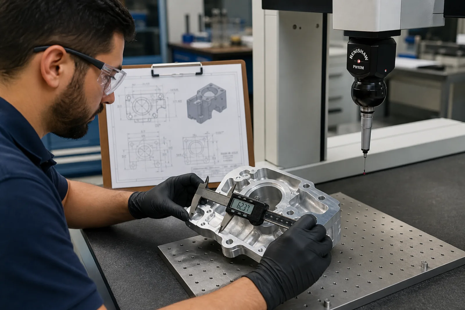
| Inspection and quality | CTQs, datums, and critical tolerances | Ensure dimensional conformance |
| Final quote | Cost, lead time, and scope | Deliver a clear, traceable proposal |
Design for manufacturability (DFM) review
Before fabricating a part, we evaluate manufacturability from a real production perspective.
This includes internal radii, cavity depth, tool accessibility, critical tolerances, deformation risk, material rigidity, and setup complexity.
If we detect optimization opportunities or possible problems during manufacturing, we communicate them before CAM programming or production begins.
The goal of DFM is not to change the design unnecessarily, but to reduce risk, time, and cost without compromising functionality.
Material and process evaluation
Each geometry and production volume requires different processes.
During technical review we evaluate whether the part should be manufactured through CNC milling, CNC turning, metal fabrication, 3D printing, or injection molding.
We also analyze compatibility between material, tolerances, finishes, and production volume to select the most efficient manufacturable strategy.
Machining and production planning
Once the CAD model is validated, we define the sequence of operations, tools, fixturing, setup orientation, and inspection criteria.
Production planning seeks to minimize re-clamping, improve repeatability, and ensure dimensional stability during manufacturing.
On complex parts, multi-axis toolpaths, tool accessibility, material deformation, and control of critical characteristics are also considered.
Quoting for prototypes and production
With complete files and clear documentation, we can deliver faster, more accurate quotes for prototypes, pilot lots, and repetitive production.
This includes manufacturability evaluation, materials, secondary processes, inspection, and delivery times.
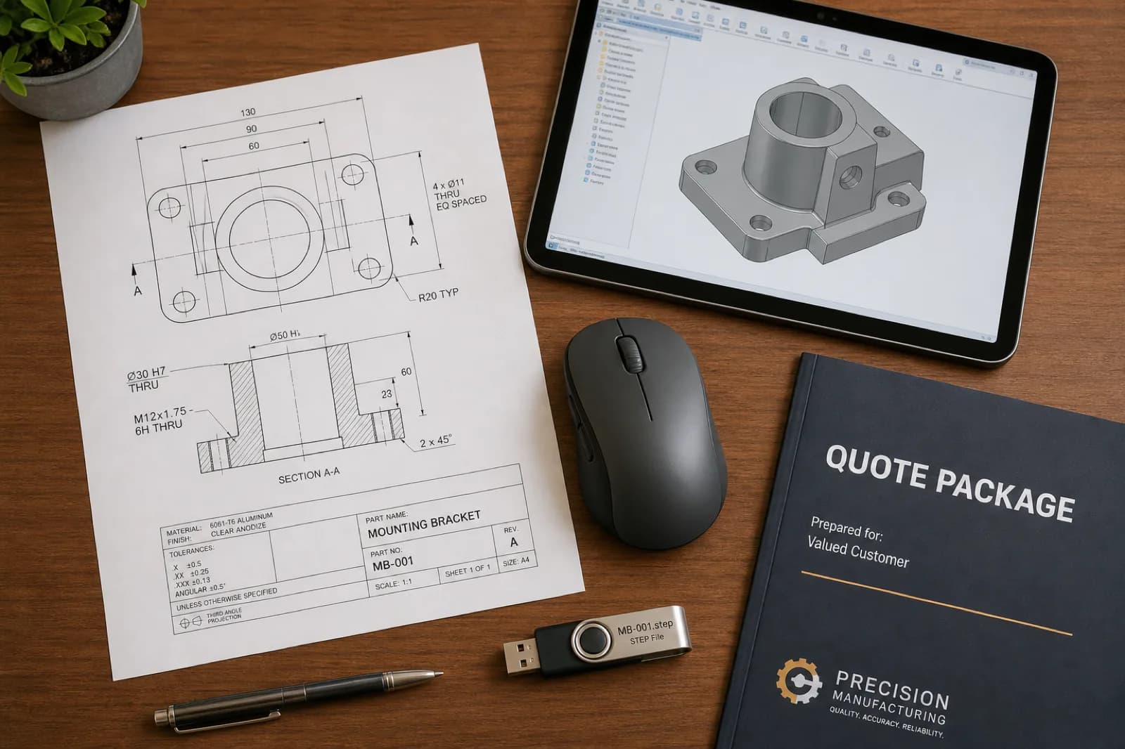
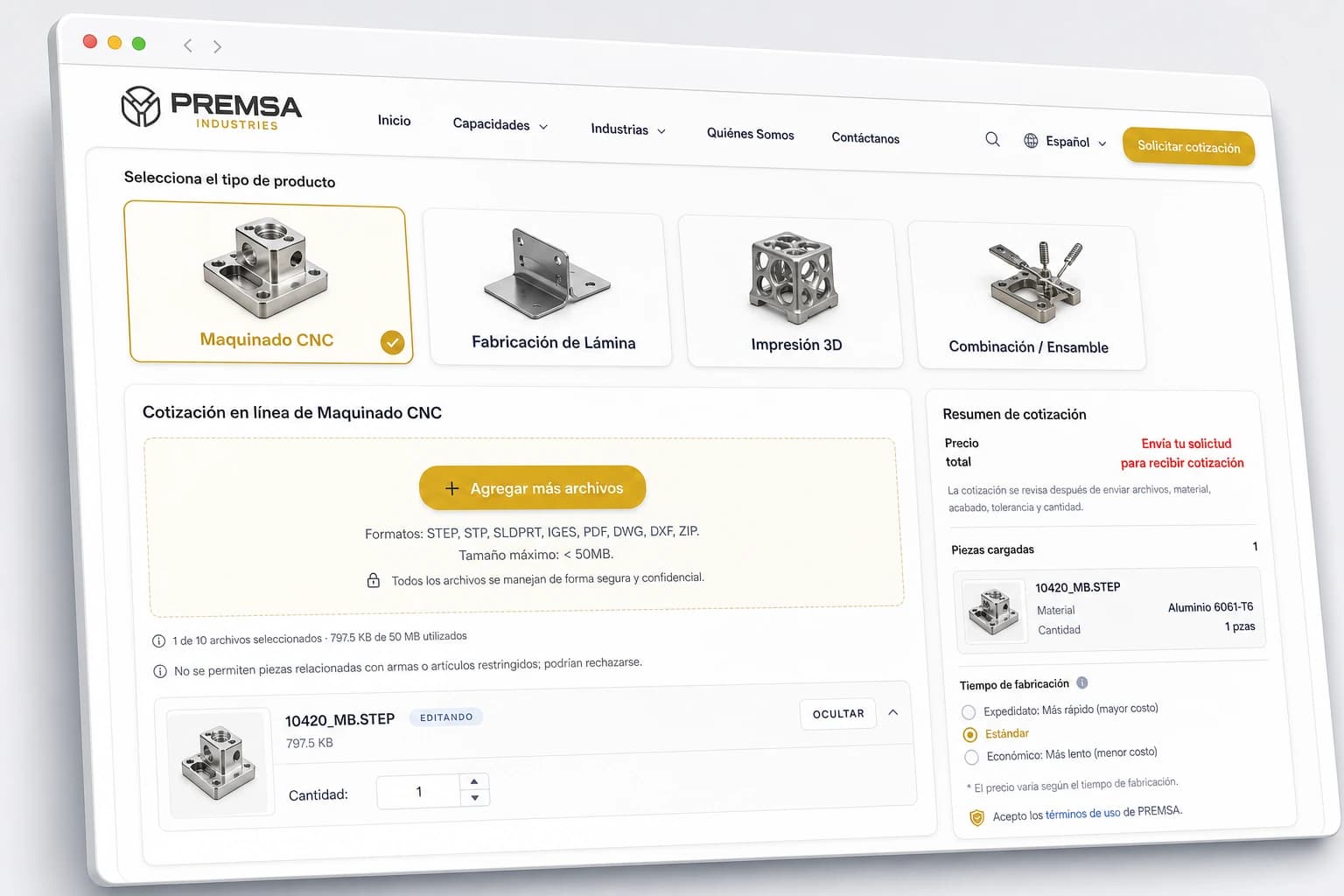
You can start the process through our online quoting by sending STEP files, technical drawings, and manufacturing specifications.
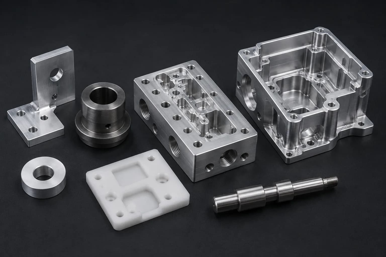
Materials and Processes Compatible with CAD Files
The same CAD file can be manufactured through completely different processes depending on geometry, material, tolerances, production volume, and functional objective.
For example, a part can start as a 3D-printed prototype, move to CNC machining for functional validation, and finally migrate to production through injection molding.
At PREMSA Industries, we use CAD files as the basis to evaluate which process offers the best combination of precision, speed, scalability, and cost.
These are some of the capabilities we frequently integrate from 3D models and technical drawings.
| Process | Ideal when… | Link |
|---|---|---|
| CNC machining | You need dimensional accuracy, tight tolerances, and engineering materials | See CNC services |
| CNC milling | The part has prismatic geometry, cavities, multiple faces, or complex features | CNC milling |
| CNC turning | Geometry is cylindrical or revolved | CNC turning |
| CNC Mill-Turn | Turning and milling operations must be combined in a single setup | CNC Mill-Turn |
| Swiss-type machining | Parts are small, long, or highly repetitive precision | Swiss-type machining |
| Sheet metal fabrication | The part starts from 2D geometry bent or cut from sheet metal | Sheet metal |
| Sheet cutting | The 2D profile defines the main part | Sheet cutting |
| Sheet metal bending | Sheet-formed parts are required | Sheet metal bending |
| 3D printing | You need rapid prototypes or geometries difficult to machine | 3D printing |
| Plastic part production | You need scalability and repetitive production | Plastic part production |
| Injection molding | Production volume justifies tooling and high repeatability | Injection molding |
Selecting the right process usually depends on multiple factors: part quantity, material, geometry, tolerances, surface finish, and target cost.
That is why, during technical review, we evaluate different manufacturing routes before defining the final production strategy.
In many industrial projects, especially in sectors such as automotive, robotics, and manufacturing, combining multiple processes within the same workflow can accelerate development and optimize costs.
Frequently Asked Questions About CAD Files and CNC Quotes
Direct answers on CAD formats, STEP export, SolidWorks machining, Fusion 360 CNC, tolerances, DFM, and quoting machined parts with PREMSA Industries.
- What file format is best for CNC?
- STEP (.STEP / .STP) is the preferred format for CNC manufacturing because it transfers precise solid geometry between CAD and CAM with excellent compatibility. We also accept Parasolid, SolidWorks, Inventor, CATIA, Creo, Siemens NX, and IGES when necessary.
- Can I quote with only an STL?
- Yes, you can attach STL as a visual reference, but for CNC machining we recommend sending STEP as the primary file. STL uses a triangulated mesh and usually requires geometric reconstruction for CAM programming.
- Do I need to send technical drawings?
- It is not always mandatory, but it is highly recommended when critical tolerances, threads, finishes, datums, or functional requirements exist. The technical drawing reduces ambiguity and speeds up quoting and inspection.
- What tolerances should I specify?
- Apply tight tolerances only on functional features and CTQs. For general geometry, standards such as ISO 2768 are usually sufficient and much more efficient from a manufacturing standpoint.
- What CAD software is compatible?
- We regularly work with SolidWorks, Fusion 360, Inventor, CATIA, Creo, Siemens NX, Onshape, and other industrial CAD systems. Exporting a clean STEP is usually enough to quote.
- How do I export STEP from Fusion 360 or SolidWorks for CNC?
- Validate units (mm or inches), export solids only, review geometry, suppress unnecessary sketches, and verify the file by importing it again before sending. We also recommend including revision in the file name.
- Can I quote Fusion 360 CNC or SolidWorks machining projects with PREMSA?
- Yes. We receive files from virtually any professional CAD platform. To speed up review and manufacturing we recommend sending STEP + PDF with material, quantity, finishes, and critical tolerances.
- What tolerances should I put on the technical drawing?
- Use general tolerances such as ISO 2768 for non-critical dimensions and define CTQs only where fits, alignments, sealing, or functional interfaces exist. Avoid applying ±0.01 mm globally if it is not truly necessary.
- Can I send complete assemblies?
- Yes. You can send complete assemblies for functional context, but we recommend clearly identifying which parts should be quoted, manufactured, or assembled. Separating individual components usually speeds up review.
- What if my model needs changes for manufacturing?
- During DFM review we can identify opportunities to improve manufacturability, reduce cost, or simplify production. If we identify risks or potential improvements, we communicate them before manufacturing.
- How do I know if my part is manufacturable?
- Factors such as tool access, cavity depth, tolerances, internal radii, and material affect manufacturability. That is why we review every project before releasing CAM programming or production.
STEP (.STEP / .STP) is the preferred format for CNC manufacturing because it transfers precise solid geometry between CAD and CAM with excellent compatibility. We also accept Parasolid, SolidWorks, Inventor, CATIA, Creo, Siemens NX, and IGES when necessary.
Yes, you can attach STL as a visual reference, but for CNC machining we recommend sending STEP as the primary file. STL uses a triangulated mesh and usually requires geometric reconstruction for CAM programming.
It is not always mandatory, but it is highly recommended when critical tolerances, threads, finishes, datums, or functional requirements exist. The technical drawing reduces ambiguity and speeds up quoting and inspection.
Apply tight tolerances only on functional features and CTQs. For general geometry, standards such as ISO 2768 are usually sufficient and much more efficient from a manufacturing standpoint.
We regularly work with SolidWorks, Fusion 360, Inventor, CATIA, Creo, Siemens NX, Onshape, and other industrial CAD systems. Exporting a clean STEP is usually enough to quote.
Validate units (mm or inches), export solids only, review geometry, suppress unnecessary sketches, and verify the file by importing it again before sending. We also recommend including revision in the file name.
Yes. We receive files from virtually any professional CAD platform. To speed up review and manufacturing we recommend sending STEP + PDF with material, quantity, finishes, and critical tolerances.
Use general tolerances such as ISO 2768 for non-critical dimensions and define CTQs only where fits, alignments, sealing, or functional interfaces exist. Avoid applying ±0.01 mm globally if it is not truly necessary.
Yes. You can send complete assemblies for functional context, but we recommend clearly identifying which parts should be quoted, manufactured, or assembled. Separating individual components usually speeds up review.
During DFM review we can identify opportunities to improve manufacturability, reduce cost, or simplify production. If we identify risks or potential improvements, we communicate them before manufacturing.
Factors such as tool access, cavity depth, tolerances, internal radii, and material affect manufacturability. That is why we review every project before releasing CAM programming or production.
Conclusion
How good CAD preparation improves cost, lead times, and manufacturability
A well-prepared CAD file is not simply an administrative requirement: it is the foundation for a fast quote, more efficient production, and parts that actually work in assembly.
Clean STEP, updated drawings, defined materials, clear CTQs, and organized documentation reduce friction across the entire manufacturing flow: DFM review, CAM programming, dimensional inspection, and repetitive production.
The clearer the technical package from the start, the less time is lost interpreting design intent and the faster the project can move toward manufacturing.
If you are also evaluating costs and production strategies, see our guides on CNC machining cost and how to get CNC parts made.
Next steps to quote CNC parts with PREMSA Industries
Upload your STEP file, add manufacturing specifications, and receive technical review for prototypes or repetitive production through our online quoting.
At PREMSA Industries we manufacture components for industries such as aerospace and defense, robotics, hardware, and manufacturing, integrating processes such as CNC machining, metal fabrication, additive manufacturing, and plastic part production.
We work with prototypes, pilot lots, and production in Mexico with support for North American supply chains.
If you are preparing or optimizing designs, see our CNC machining design guide.

Written by
Adrian Cavazos and the PREMSA Engineering Team
Adrian Cavazos, founder of PREMSA Industries, leads a manufacturing engineering team specialized in CNC machining, metal fabrication, and production-ready solutions. The team works closely with customers to optimize designs, improve manufacturability (DFM), and ensure reliable, scalable production from prototypes to volume manufacturing.