There is an uncomfortable truth that rarely comes up in a procurement meeting or during a quote review: most expensive CNC parts are not expensive because of material or because the supplier has excessive margins. They are expensive because they were designed without considering how they will be manufactured.
When a quote seems too high, the natural reaction is usually to find another supplier, ask for discounts, or renegotiate quantities. In many cases, however, the real problem was already defined weeks or months earlier, when someone modeled the part in CAD. Every deep pocket, every unnecessary tolerance, every additional orientation, and every excessive specification becomes machine time, tooling, inspection, and manufacturing risk—the same kind of friction a well-prepared package avoids, as covered in our guide to CAD files for CNC machining.
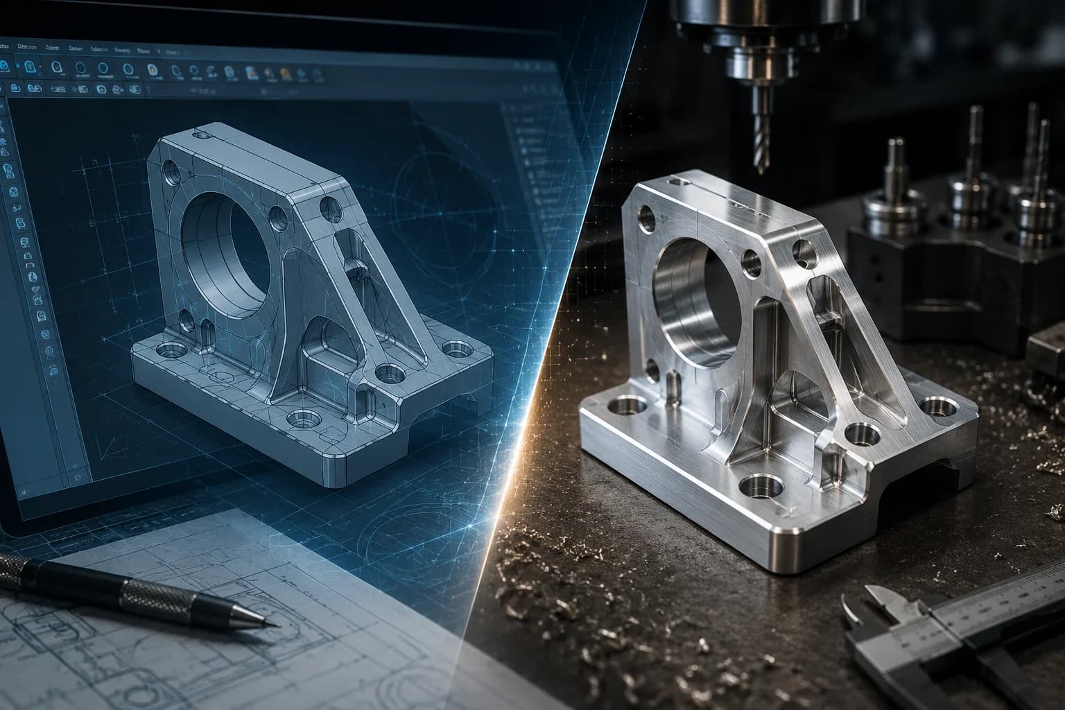
The reality is that CNC part cost is not born on the shop floor. It is born in the design. Long before the first bar reaches the machine or the first CAM program is generated, much of the budget has already been determined by seemingly small decisions made during engineering. At PREMSA Industries we integrate DFM review from the quote stage because that is where savings are still inexpensive.
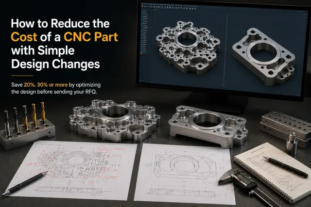
The good news is that reducing cost does not always require radical redesigns. In many projects, simple adjustments to fillets, setups, tolerances, or geometry can reduce manufacturing cost by 20%, 30%, or even more without affecting strength, function, or performance. This guide explores the five design changes that usually generate the greatest economic impact before you send an RFQ; to go deeper on each criterion, cross-reference it with the CNC machining design guide.
Five design changes that reduce CNC cost
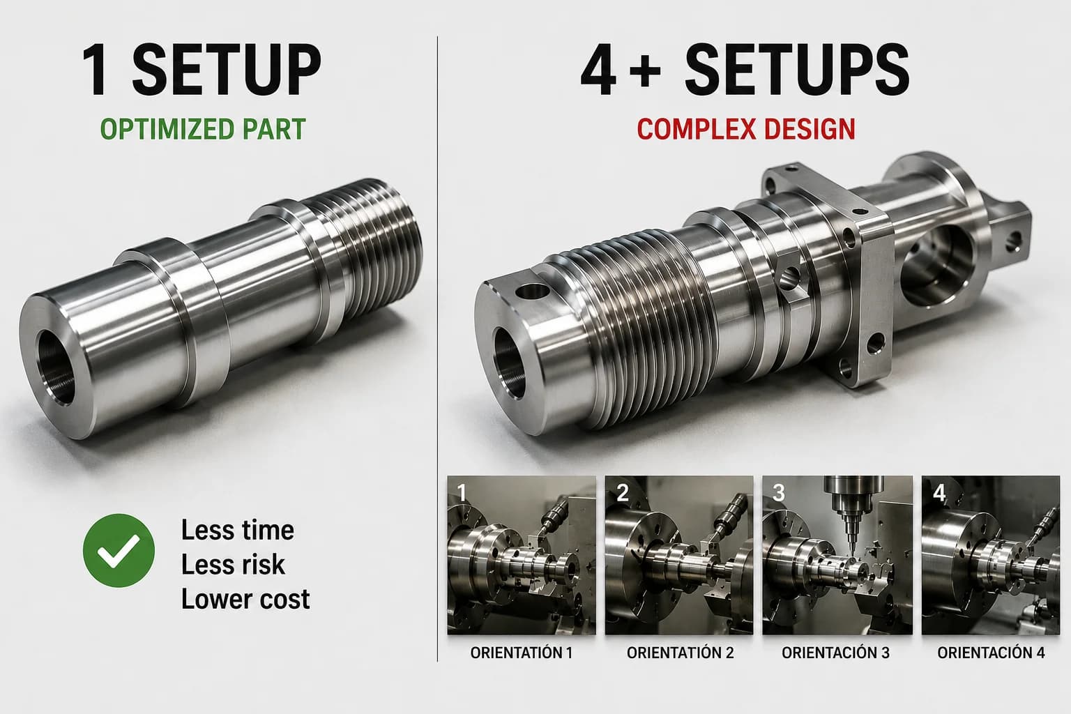
- Design parts that require fewer setups — each orientation adds preparation time and alignment risk.
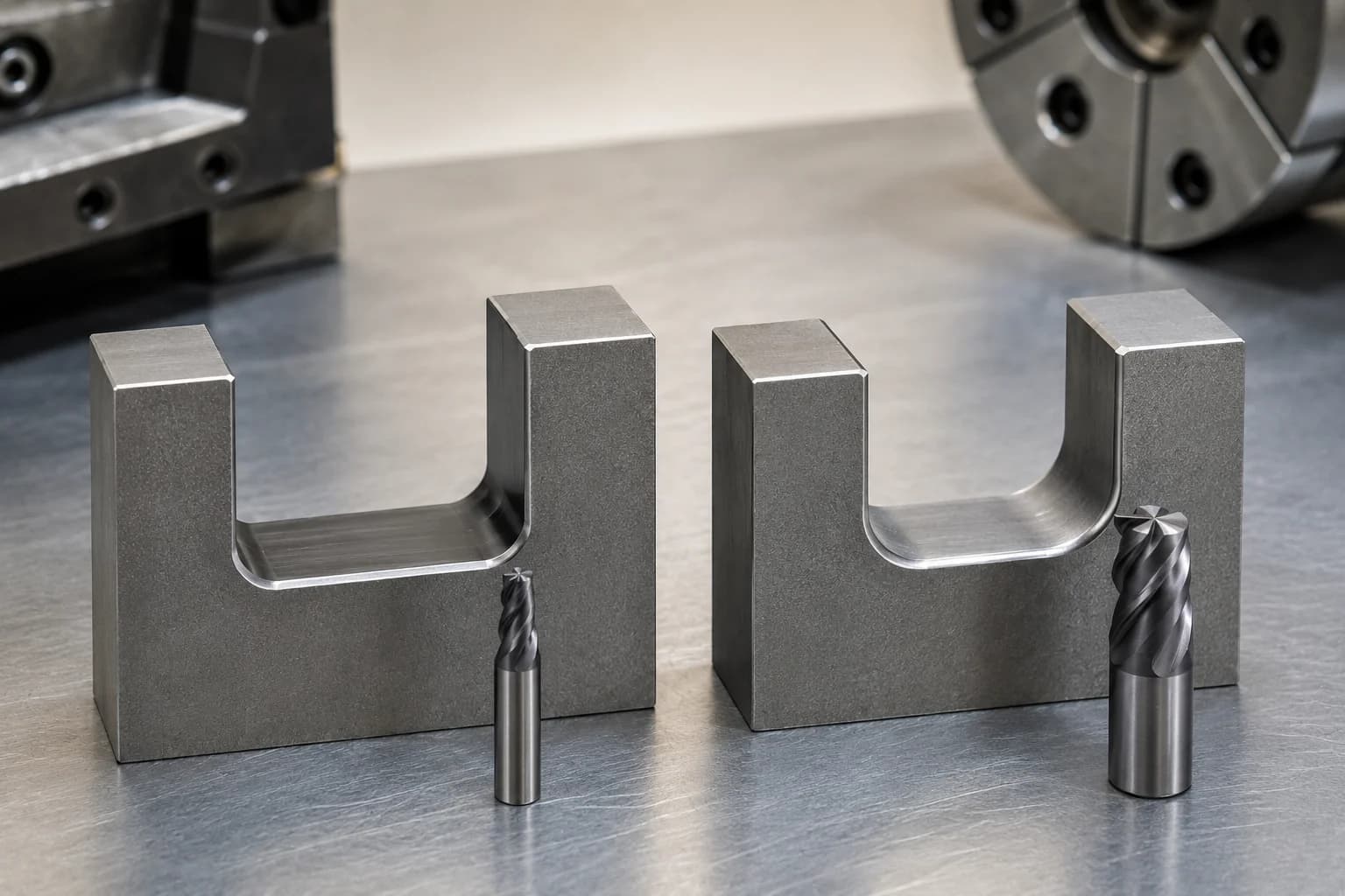
- Use fillet radii compatible with standard tools — avoid radii that force special tooling or EDM.
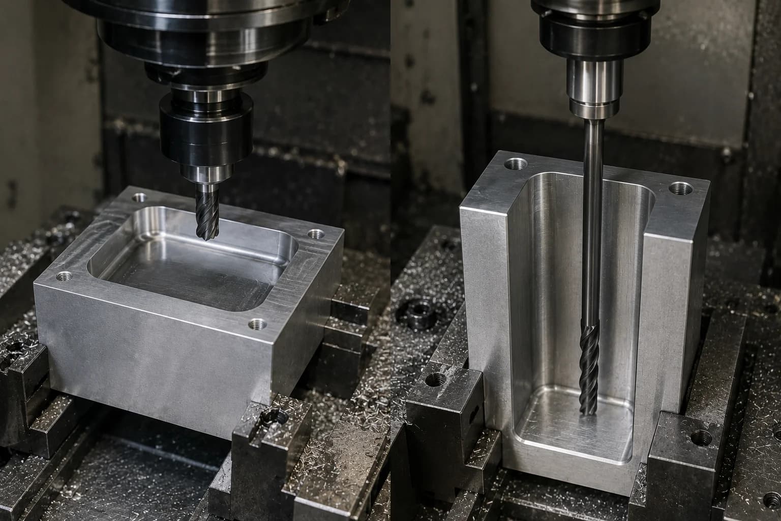
- Reduce pocket depth — shallower pockets mean faster roughing and more stable machining.
- Tolerances must earn their place — tighten limits only on dimensions that control function.
- Remove specifications that add no functional value — unnecessary finishes and notes inflate cost.
The most common mistake: trying to reduce cost after quoting
What happens when the design is already frozen
Once a design has been approved for validation, released for production, or committed to a customer, real savings opportunities drop sharply. At that point, conversations usually focus on discounts, commercial negotiation, or finding alternative suppliers. The problem is that none of those actions eliminate programming hours, machine time, complex setups, or inspections demanded by the design itself.
If a part requires five different orientations to be machined, includes extremely small internal fillets, or demands high-precision tolerances on surfaces that do not affect function, the supplier is simply reflecting those requirements in the quote. Changing shops may shift the price slightly, but it does not remove the inherent complexity of the design—which is why it pays to review manufacturability before freezing the CAD, as detailed in the CNC machining design guide.
For that reason, projects that integrate manufacturability criteria from the earliest stages usually reach production with fewer revisions, less rework, and significantly more competitive costs. If the design is already ready to validate, you can request a quote with DFM review and catch those friction points before committing to volume.
Why CAD has more impact than negotiation
Negotiating a quote may move a few percentage points. Optimizing the design can completely change the cost structure.
A supplier can adjust margins, find internal efficiencies, or consolidate operations, but they cannot physically eliminate the time required to manufacture a complex geometry. When a part requires special tools, multiple setups, tight tolerances, or intensive inspection, those costs exist regardless of the supplier name—and they show up in any CNC machining service quoting the same geometry.
That is why teams that apply design for manufacturability (DFM) principles from engineering usually get more consistent quotes, shorter lead times, and fewer surprises during production. Before negotiating price, it usually makes sense to ask whether the design is forcing the shop to work harder than necessary.
If you want to understand what factors actually drive CNC part cost, complement this guide with what affects CNC machined part cost the most and the CNC machining cost breakdown.
| Action | Typical cost impact | Difficulty |
|---|---|---|
| Negotiate price with the supplier | Low | Low |
| Change suppliers | Low to medium | Medium |
| Optimize design (DFM) | Very high | Medium |
| Reduce setups and orientations | Very high | Medium |
| Optimize tolerances | High | Low |
| Remove unnecessary specifications | High | Low |
| Increase batch volume | High | Medium |
Most meaningful CNC savings happen before the first part is manufactured. Once the design is frozen, the room to maneuver shrinks considerably.
Change #1: Design parts that require fewer setups
If you could apply only one design change to reduce CNC part cost, it would probably be this: reduce the number of setups required to manufacture the part. It is one of the highest-weight criteria in the CNC machining design guide and in real DFM reviews.
Every time a part must be removed from the fixture, rotated, realigned, and verified, you add preparation minutes, accumulated risk, and dimensional variation. From the shop's perspective, an additional setup is not simply flipping a part. It means re-establishing references, validating positions, checking critical dimensions, and ensuring the next operation maintains geometric relationship with the previous ones—especially in CNC milling of prismatic geometry.
That is why two parts with the same material, size, and machining volume can end up with radically different costs if one requires two setups and the other five.
What is a setup?
A setup is the complete set of activities required to machine a part from a specific orientation. It includes preparing the workholding, mounting the material, establishing work offsets, loading tools, running the program, and verifying that machined features meet specification before moving to the next orientation.
From a cost perspective, each setup acts as an additional fixed cost within the work order. The more setups a part requires, the more time is invested before a single good unit is produced.
A part that can be completed in one or two orientations is usually considerably more economical than another with the same amount of material but multiple faces inaccessible from a single fixturing approach.
How setups multiply cost
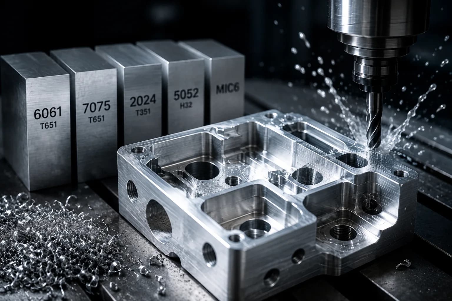
Imagine two brackets machined from 6061-T6 aluminum. Both have similar dimensions, use the same raw stock, and serve the same function in an assembly. The difference is how they were designed for manufacturing.
| Factor | Part A | Part B |
|---|---|---|
| Setups required | 2 | 5 |
| CAM programming | Simple | Multiple operations |
| Fixtures or workholding | Standard | Special or multiple |
| Preparation time | Low | High |
| Accumulated error risk | Low | High |
| Relative cost | 100% | 145-180% |
Part B is not just slightly more expensive. Each additional setup means re-clamping the part, re-referencing critical dimensions, and re-validating that previous operations remain correctly aligned. In prototypes the impact is often enormous because fixed preparation cost is spread across few units. In production it still matters, especially when cycle times are short and preparation represents a significant share of total cost.
An additional setup does not just add preparation minutes. It also increases the risk of errors, rework, and additional inspections.
How to identify unnecessary setups in CAD
A good practice during design is to imagine how the tool will reach each important feature on the part. If you constantly need to mentally rotate the component to machine a detail, there is a good chance the shop will also need an additional orientation to make it. The orientation and workholding section of the CNC machining design guide goes deeper on how to anticipate those rotations from CAD.
- Analyze from which direction the tool can reach each critical feature.
- Evaluate whether multiple operations can be performed from the same orientation.
- Avoid isolated details that force the part to be rotated solely to machine a minor feature.
- Align holes, bores, and threads on common axes when function allows (for rotational parts, also review CNC turning criteria).
- Design clear reference surfaces to simplify workholding and inspection.
- Ask during DFM review how many setups the part will actually require.
| Typical setups | Cost impact |
|---|---|
| 1-2 | Low |
| 3-4 | Medium |
| 5 or more | High |
Change #2: Use fillet radii compatible with standard tools
After setups, few design changes have as immediate an impact on cost as internal fillets. It is one of those decisions that seems insignificant in CAD but can force the shop to use smaller tools, slower cycles, and considerably less efficient machining strategies—exactly what the CNC machining design guide documents for fillets, corners, and pockets.
Most engineers think about the final geometry of the part. The shop, by contrast, must think about the tool required to create that geometry. That is where many cost differences begin.
Why perfect corners are expensive
CNC end mills are cylindrical tools. That means they naturally produce internal radii. When a CAD model includes extremely small or nearly square internal corners, the shop is forced to use smaller-diameter tools to approximate that geometry.
The problem is that a smaller tool is usually also less rigid, slower, and more vulnerable to vibration or breakage. What looks like a simple 1 mm fillet on screen can translate into multiple additional passes, reduced feed rates, and a significant drop in productivity.
In other words: small internal corners do not just affect geometry. They directly affect machine time.
The fastest tool is usually the largest one that can fit the geometry. Every time you force the shop to use a smaller tool, you are usually increasing cost.
1 mm fillet vs 6 mm fillet
Consider a pocket machined in aluminum. If the design requires 1 mm internal fillets, a significantly smaller tool will probably be needed than if the fillet were 6 mm.
Although both parts may look nearly identical to the end user, the manufacturing difference is enormous: more rigid tools allow higher feed rates, better chip evacuation, less vibration, less wear, and considerably shorter cycle times.
Often the assembly, screw, bearing, or adjacent part does not even interact with that internal fillet. Yet the cost to manufacture it changes significantly.
| Internal fillet | Typical tool | Cost impact |
|---|---|---|
| 1 mm | Small | High |
| 3 mm | Standard | Medium |
| 6 mm | Rigid and productive | Low |
The goal is not to increase fillets indiscriminately. The goal is to use the largest fillet possible without affecting product function. In many cases, that simple adjustment can reduce cycle time without changing anything about part performance.
Which fillets tend to be most economical
The most economical fillets are usually those compatible with tools the shop already uses routinely. When the design forces the use of very specific or uncommon tools, programming and manufacturing cost tends to rise.
During a DFM review it is worth asking whether the specified fillet actually adds functional value or was simply a decision made during CAD modeling. If you need a quick reference for process-recommended fillets, the CNC machining design guide is the usual starting point for engineering teams.
- Use fillets compatible with standard tools whenever function allows.
- Avoid sequences of tiny fillets that force multiple tool changes.
- In deep pockets, aim for fillets compatible with rigid, productive tools.
- Clearly document critical fillets on the drawing to avoid interpretation issues during CAM programming.
- If the fillet does not affect assembly or performance, consider increasing it during DFM review.
| Internal fillet (example) | Typical impact |
|---|---|
| 1 mm | High |
| 3 mm | Medium |
| 6 mm or larger | Low |
If a part includes multiple pockets or internal geometries, optimizing fillets is often one of the fastest ways to reduce cycle time without affecting function. In many projects, savings from more manufacturing-friendly fillets far exceed any discount obtained through commercial negotiation.
Change #3: Reduce pocket depth
Deep pockets are one of the most common design mistakes when optimizing a part from CAD alone. On screen they look harmless. On the machine they often become a combination of long tools, conservative feed rates, vibration, and significantly longer cycle times—the same pattern that makes many CNC milling operations expensive.
In many projects, a deep pocket can cost more than several complex operations combined. Not because it removes more material, but because it forces that material to be machined in a much less efficient way. The 3×D rule and pocket examples are developed in the CNC machining design guide.
The rule many engineers discover too late
In CNC milling there is a relationship that appears constantly during DFM reviews: the relationship between pocket depth and the diameter of the tool required to machine it.
As a general reference, many shops consider a depth close to 3 times the tool diameter (3×D) to usually stay within an efficient zone for productivity, rigidity, and dimensional control.
That means a 30 mm deep pocket normally benefits from a tool close to 10 mm in diameter. When the design forces a much smaller tool to reach that same depth, costs usually rise quickly.
Depth alone does not make a part expensive. What makes a part expensive is the tool you must use to reach that depth.
What happens when a tool works too deep
As a tool becomes longer relative to its diameter, it loses rigidity. To avoid vibration, breakage, and deflection, the CAM programmer is often forced to reduce feed rates, cut depths, and effective material removal rates.
The result is a part that takes longer to manufacture even when the geometry looks simple.
- Longer tools → less rigidity and more deflection.
- More conservative feed rates → direct increase in cycle time.
- More machining passes → greater wear and lower productivity.
- Higher vibration risk (chatter) → worse surface finish and harder-to-control tolerances.
- More difficult chip evacuation → especially in narrow, deep pockets.
- Higher tool breakage risk → especially in difficult-to-machine materials.
How a deep pocket can double cycle time
Two pockets can remove nearly the same volume of material and still generate completely different costs.
A shallow pocket allows short, rigid, aggressive tools. A deep pocket forces long tools, conservative toolpaths, and multiple additional passes.
From the buyer's perspective both parts look similar. From manufacturing's perspective they can represent hours of machine time difference across a production run.
| Feature | Optimized pocket | Deep pocket |
|---|---|---|
| Depth | 15 mm | 40 mm |
| Tool | Short and rigid | Long and flexible |
| Material removal rate | High | Low |
| Vibration risk | Low | High |
| Relative cycle time | 100% | 180-250% |
Before increasing pocket depth, ask whether function truly requires it. In many cases it is possible to split geometry into levels, slightly increase the internal fillet, modify local wall thickness, or redesign the part to maintain the same function with much more efficient manufacturing.
Quick guide: recommended depth vs tool diameter
| Tool diameter | Approximate efficient depth |
|---|---|
| 6 mm | ≈ 18 mm |
| 8 mm | ≈ 24 mm |
| 10 mm | ≈ 30 mm |
| 12 mm | ≈ 36 mm |
These values are not absolute limits. Materials such as Grade 5 titanium, stainless steel 316, thin walls, or demanding tolerances may require more conservative ratios. However, they serve as an excellent initial reference during design to spot potentially expensive pockets before requesting a quote. To compare machinability across alloys, review the manufacturing materials catalog.
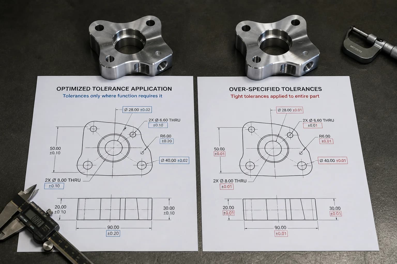
Change #4: Tolerances must earn their place
Few design decisions affect manufacturing cost as much as tolerances. And at the same time, few are used as poorly—even when the rest of the design follows good practices from the CNC machining design guide.
In many RFQs we see parts where nearly every dimension is treated as critical. The result is a part that requires more programming time, more finishing passes, more inspection, and less margin to manufacture efficiently.
The reality is simple: not every dimension has the same value for product function. When everything is critical, nothing is truly critical.
The mistake we see in many RFQs
One of the most common patterns in CNC quotes is drawings where nearly the entire part is controlled with extremely tight tolerances—the same mistake we address in the CNC machining tolerances guide.
A drawing that specifies ±0.01 mm on every dimension forces the shop to manufacture every surface as if it were a critical assembly feature. That means more stable tools, additional finishing strategies, more frequent inspections, and a higher probability of rejection.
The problem is that often only a few dimensions actually affect how the part works. The rest could be manufactured with perfectly acceptable general tolerances at a fraction of the cost.
The best tolerance is not the tightest one. It is the widest one that still lets the part perform its function.
Functional tolerances vs cosmetic tolerances
A good engineering practice is to clearly distinguish which dimensions affect real product performance and which simply describe geometry.
Functional tolerances control features that participate directly in assembly, alignment, sealing, motion, or load transfer. Cosmetic tolerances, by contrast, may influence appearance or perceived quality without changing how the component works.
When both receive the same level of dimensional control, cost increases without a proportional benefit.
| Feature | Is tight tolerance justified? |
|---|---|
| Bearing bore | Yes |
| Sealing surface | Yes |
| Assembly hole location | Yes |
| Cosmetic face with no mechanical function | Usually not |
| Non-critical external dimensions | Usually not |
When a tight tolerance is worth it
Tight tolerances exist for a reason. In the right applications they are absolutely necessary. The problem appears when they are applied by default across the entire part.
A tight tolerance is usually justified when a dimensional error can cause assembly failure, leaks, premature wear, or loss of performance.
- Assembly interfaces where relative position is critical.
- Bores for bearings, bushings, or precision components.
- Hydraulic or pneumatic sealing surfaces.
- Features subject to accumulated tolerance chains.
- Components that require high repeatability across production batches.
- Parts inspected with CMM or statistical process control systems.
How a tighter tolerance increases cost
As tolerance becomes more demanding, the shop loses margin to manufacture efficiently. Cut parameters must be reduced, temperature controlled, more stable tools used, and inspections performed more frequently.
In many cases, the cost increase does not come from machining itself, but from the additional time spent verifying that the part meets specification.
| Typical tolerance | Relative impact |
|---|---|
| ±0.25 mm | Low |
| ±0.10 mm | Medium |
| ±0.05 mm | High |
| ±0.01 mm | Very high |
Before specifying a particularly demanding tolerance, ask what would happen if that dimension varied slightly more. If the answer is "nothing important," there is probably an opportunity to reduce cost without affecting product function.
To go deeper on tolerancing strategies, adjustments, and dimensional control, see our CNC machining tolerances guide.
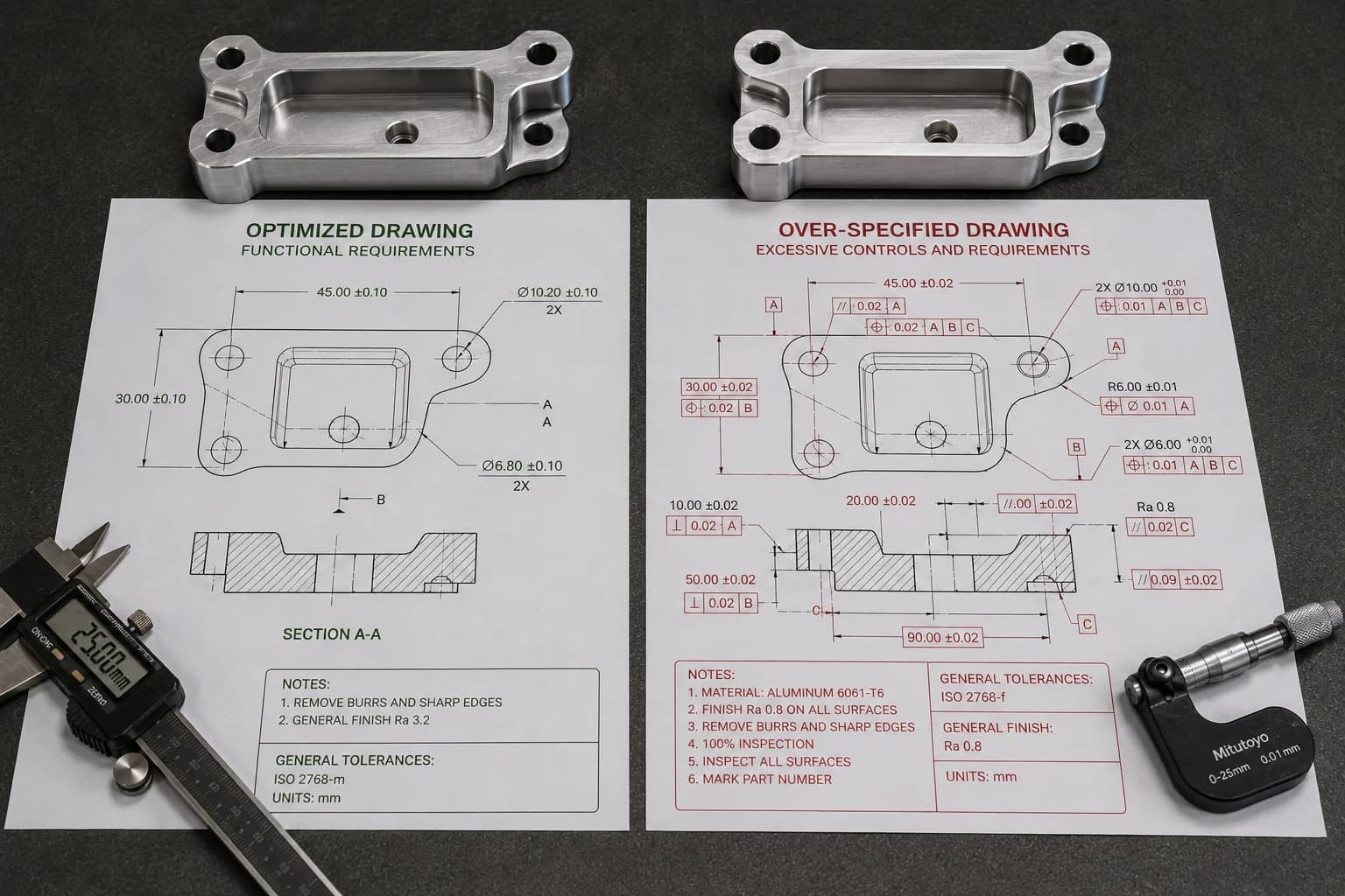
Change #5: Remove specifications that add no functional value
Many parts do not become expensive because of geometry, but because of what the drawing demands around it. Extremely fine surface finishes, unnecessary dimensional reports, full inspections, excessive geometric requirements, or specifications copied from previous projects often increase cost without delivering real product benefits—a topic separate from geometry, but equally relevant in the CNC machining design guide.
In manufacturing there is a simple rule: every additional requirement must justify the cost it creates. If a specification does not improve performance, reliability, safety, or assembly capability, it probably deserves a second look. To understand how those requirements translate into quote line items, also review what affects CNC machined part cost the most.
The invisible cost of excessive requirements
The easiest costs to identify are usually material and machine time. The hardest to detect appear in drawing details.
A more demanding surface roughness may require additional tools or finishing passes. A full dimensional report can consume more metrology time than machining itself. An unnecessarily strict geometric requirement can force the shop to run slower, inspect more, and scrap perfectly functional parts.
The problem is that these costs are rarely obvious during design. They usually appear when the quote arrives.
Every additional line on a drawing can become machine time, inspection time, or documentation time.
Common examples of over-specification
- Ra 0.4 μm surface roughness across the entire part when only one surface interacts with a seal or bearing.
- Full CMM report for a prototype where only a few dimensions are functional.
- Mirror finish on areas that will later be painted, covered, or hidden inside the assembly.
- Extremely strict GD&T inherited from another project with completely different requirements.
- Premium surface finishes applied to the entire part when only certain zones are visible or critical.
- 100% dimensional inspection on low-volume components where functional sampling would be sufficient.
When a specification actually adds value
Demanding specifications exist for a reason. The problem is not using them—it is applying them where they create no benefit.
A sealing surface may justify strict roughness. A bearing bore may require precise geometric control. An aerospace component may need full traceability. In those cases the additional cost is backed by a real functional need.
The right question during a DFM review is usually simple: if we relax this specification, what stops working? If the answer is "nothing important," there is probably a savings opportunity.
| Requirement | Always necessary? |
|---|---|
| Ra 0.4 μm on all surfaces | No |
| Full CMM report on prototypes | No |
| ±0.01 mm across the entire part | No |
| Mirror finish | No |
| 100% dimensional inspection | No |
| Strict GD&T on non-functional features | No |
Where to invest precision
The most efficient strategy is not to remove requirements, but to concentrate them where they actually create value.
Sealing surfaces, precision bores, critical assembly interfaces, and features related to safety or performance deserve special attention. The rest of the part can be manufactured with more reasonable specifications that reduce machine time, inspection, and documentation without compromising product function.
If your project requires surface treatments, cosmetic finishes, or corrosion protection, also review our manufacturing finishes library to understand when each process adds value and when it only increases cost.
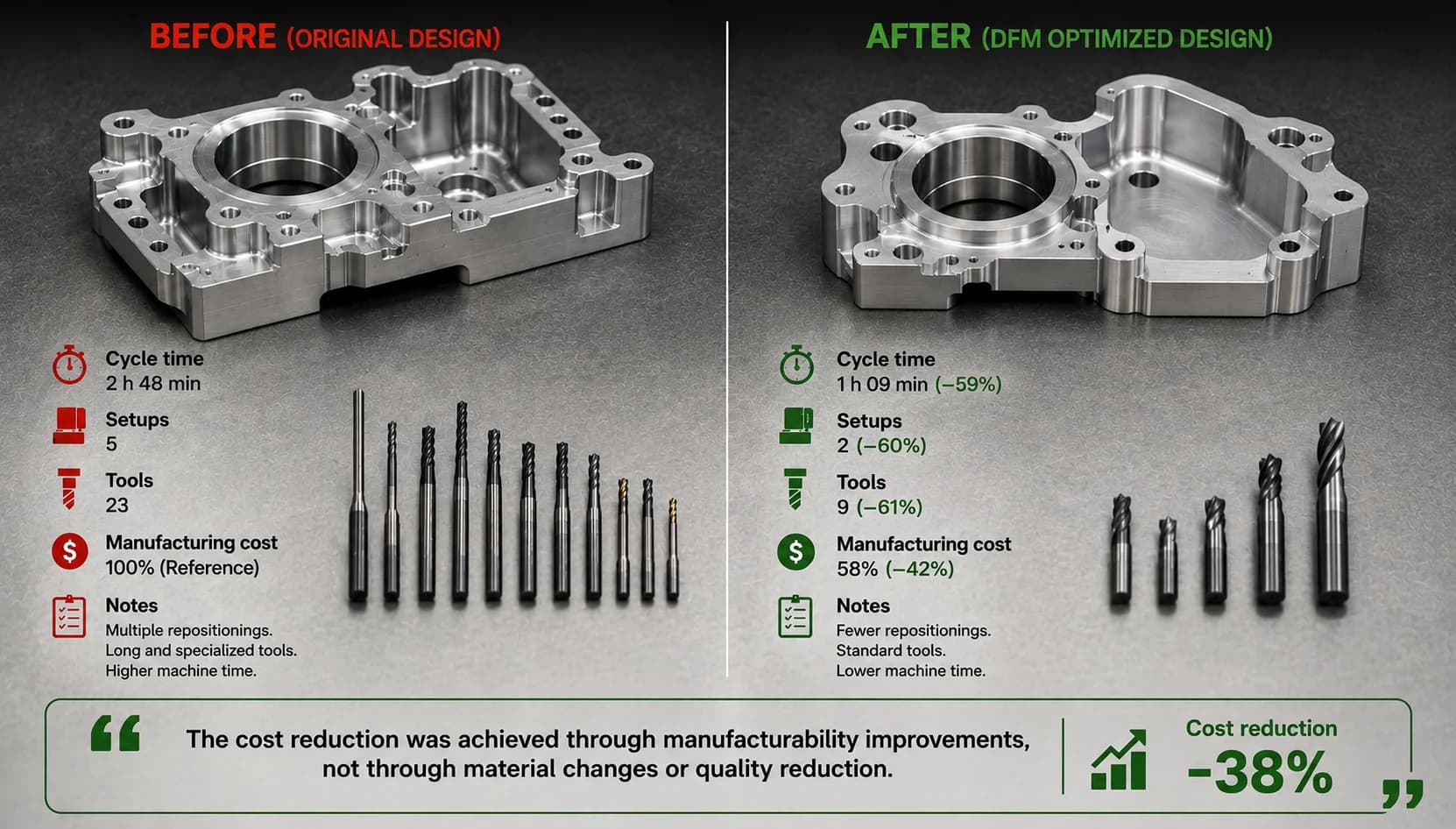
Case study: how a DFM review reduced cost by 38%
To understand why design usually has more impact than negotiation, consider a typical scenario.
An engineering team requested a quote for a bracket machined from 6061-T6 aluminum. The part performed its function perfectly, but the first quote came back considerably higher than expected. From procurement, the initial reaction was the usual one: ask for discounts and compare suppliers.
Before re-quoting, however, a DFM review focused exclusively on manufacturability was performed. The goal was not to reduce quality or change component function. The goal was to identify features that were adding cost without delivering real value.
What changed
During the review several optimization opportunities were identified. None affected structural strength, assembly, or operational performance of the bracket.
- Unnecessary orientations were removed to reduce the number of setups.
- Internal fillets were increased to allow more rigid, productive tools.
- Some pockets were simplified to reduce machining time.
- Tight tolerances were removed from dimensions that did not affect assembly.
- The total number of tools required to manufacture the part was reduced.
| Feature | Original design | Optimized design |
|---|---|---|
| Setups | 5 | 2 |
| Internal fillets | 1 mm | 6 mm |
| Estimated cycle time | 32 min | 18 min |
| Distinct tools | 8 | 4 |
| Relative cost | 100% | 62% |
The result
The material stayed exactly the same. Mechanical strength stayed the same. Bracket function stayed the same.
What changed was how it was manufactured within the CNC machining services flow with integrated DFM review.
By reducing setups, using more productive tools, and concentrating precision only where it was needed, the shop could manufacture the part with less preparation time, fewer tool changes, and lower inspection load.
The result was an approximate 38% reduction in manufacturing cost, achieved before a single part was made—the same kind of optimization you can validate when you request a quote with DFM review.
The biggest savings did not come from negotiating the quote. They came from eliminating unnecessary work before the part reached the machine.
The lesson
These results are not exceptional. In many projects, the greatest savings opportunities appear during an early DFM review, when there is still freedom to adjust geometry, tolerances, and manufacturing strategy—the approach we apply at PREMSA Industries from the first file review.
Once the design is frozen, most of those opportunities disappear and the team ends up trying to recover through negotiation what could have been avoided from engineering. The CNC machining design guide summarizes the criteria that usually move the needle in cases like this.
Which change usually generates the greatest savings?
After reviewing hundreds of parts and industrial RFQs, one thing repeats constantly: the biggest savings rarely come from negotiating a few percentage points with the supplier. They usually appear when unnecessary manufacturing work is removed.
Every setup eliminated, every tool change avoided, every cycle minute removed, and every unnecessary tolerance removed from the drawing becomes real savings. That is why the most efficient engineering teams do not wait for a quote to think about cost: they start optimizing from CAD. In prototypes and short runs that margin still matters: low-volume CNC machining without MOQ does not eliminate the need for an efficient design.
| Improvement | Savings potential | Implementation speed |
|---|---|---|
| Reduce setups | Very high | Medium |
| Reduce cycle time | Very high | Medium |
| Optimize internal fillets | High | High |
| Optimize tolerances and GD&T | High | High |
| Remove unnecessary requirements | High | High |
| Select a more machinable material | Medium | Medium |
The fastest way to reduce part cost is usually to eliminate work the machine should never have had to do.
If a part is still expensive after optimizing material and volume, it usually pays to review setups, cycle time, and tolerances before negotiating price again. In most cases that is where the most important savings opportunities are—and that is where the CNC machining design guide and the CNC machining cost breakdown complement each other best.
DFM checklist before sending an RFQ
Before uploading your STEP file or sending a technical package to manufacturing, spend five minutes reviewing this list. A single "no" answer can represent unnecessary machine hours or hundreds of dollars of difference in a quote. If you are still assembling the package, the guides on how to get CNC parts made and CAD files for CNC machining help make DFM review faster.
- Does the part use the fewest possible setups?
- Are internal fillets compatible with standard tools?
- Do pockets respect reasonable depth-to-diameter ratios?
- Are tight tolerances limited to functional features?
- Are critical surfaces clearly identified?
- Is surface roughness specified only where it adds value?
- Is the material aligned with the real application and not over-specified? (see manufacturing materials if unsure)
- Are the drawing and STEP model consistent with each other?
- Are finish, inspection, and treatment notes truly necessary?
- Was a DFM review performed before requesting a quote?
If several answers raise doubts, there is probably an optimization opportunity before manufacturing. The CNC machining design guide goes deeper on each of these points with practical examples and manufacturing recommendations. When the checklist is clear, request a quote with your STEP to validate manufacturability and cost in the same package.
FAQ
Frequently asked questions about reducing CNC machining cost
Quick answers for engineering, design, and procurement teams before sending an RFQ.
- Which design change usually reduces CNC part cost the most?
- In most projects, reducing the number of setups and lowering cycle time generate the greatest economic impact. These improvements directly affect machine hours, programming, preparation, and inspection. The CNC machining design guide prioritizes these criteria with practical examples.
- Do tight tolerances always increase price?
- Practically yes. As a tolerance becomes more demanding, finishing operations, inspection frequency, and rejection risk increase. The recommendation is to reserve them for functional features, as explained in the CNC machining tolerances guide.
- How many setups is too many?
- As a rule of thumb, 1 or 2 setups are usually efficient. Between 3 and 4 may be reasonable depending on geometry. When a part requires 5 or more setups, it is usually worth reviewing the design—the orientation section in the CNC machining design guide helps detect unnecessary rotations.
- What maximum depth should a CNC pocket have?
- It depends on material and tool, but many shops use an initial reference ratio close to 3 times the tool diameter (3×D). Greater depths usually imply longer tools, slower cycles, and higher costs; review pockets and depths in the CNC machining design guide.
- Is a DFM review worth it before requesting a quote?
- Yes. An early DFM review usually identifies manufacturability issues before they become cost. It is one of the highest-return activities in the product development process. At PREMSA Industries we integrate it into request a quote with your STEP file.
In most projects, reducing the number of setups and lowering cycle time generate the greatest economic impact. These improvements directly affect machine hours, programming, preparation, and inspection. The CNC machining design guide prioritizes these criteria with practical examples.
Practically yes. As a tolerance becomes more demanding, finishing operations, inspection frequency, and rejection risk increase. The recommendation is to reserve them for functional features, as explained in the CNC machining tolerances guide.
As a rule of thumb, 1 or 2 setups are usually efficient. Between 3 and 4 may be reasonable depending on geometry. When a part requires 5 or more setups, it is usually worth reviewing the design—the orientation section in the CNC machining design guide helps detect unnecessary rotations.
It depends on material and tool, but many shops use an initial reference ratio close to 3 times the tool diameter (3×D). Greater depths usually imply longer tools, slower cycles, and higher costs; review pockets and depths in the CNC machining design guide.
Yes. An early DFM review usually identifies manufacturability issues before they become cost. It is one of the highest-return activities in the product development process. At PREMSA Industries we integrate it into request a quote with your STEP file.
Conclusion
Most expensive parts are not born on the machine. They are born in design decisions that force the shop to invest more time, more tools, more inspection, and more preparation than necessary.
Reducing setups, optimizing fillets, controlling pocket depth, applying smart tolerances, and removing unnecessary specifications are changes that can completely transform the economics of a part without changing its function. These are the same principles we apply in CNC machining services with DFM review from the quote stage at PREMSA Industries.
What matters is understanding that reducing cost does not mean sacrificing quality. It means concentrating resources where they actually create value. When manufacturability is considered from the start of the project, the result is usually a more competitive part that is easier to manufacture and more predictable in production. The CNC machining design guide is the most complete reference for standardizing those criteria across your team.
The best discount in CNC machining rarely appears in a negotiation. It almost always appears in a smart design review.
If you want to understand how these factors show up in a real quote, see these related articles:
- What affects CNC machined part cost most — machine time, setups, and geometry.
- CNC machining material cost guide — how much raw stock affects final price.
- How CNC machine hourly cost is calculated — from hourly rate to price per part.
- CNC machining in Monterrey — local quoting and manufacturing.

Written by
Adrian Cavazos and the PREMSA Engineering Team
Adrian Cavazos, founder of PREMSA Industries, leads a manufacturing engineering team specialized in CNC machining, metal fabrication, and production-ready solutions. The team works closely with customers to optimize designs, improve manufacturability (DFM), and ensure reliable, scalable production from prototypes through volume manufacturing.