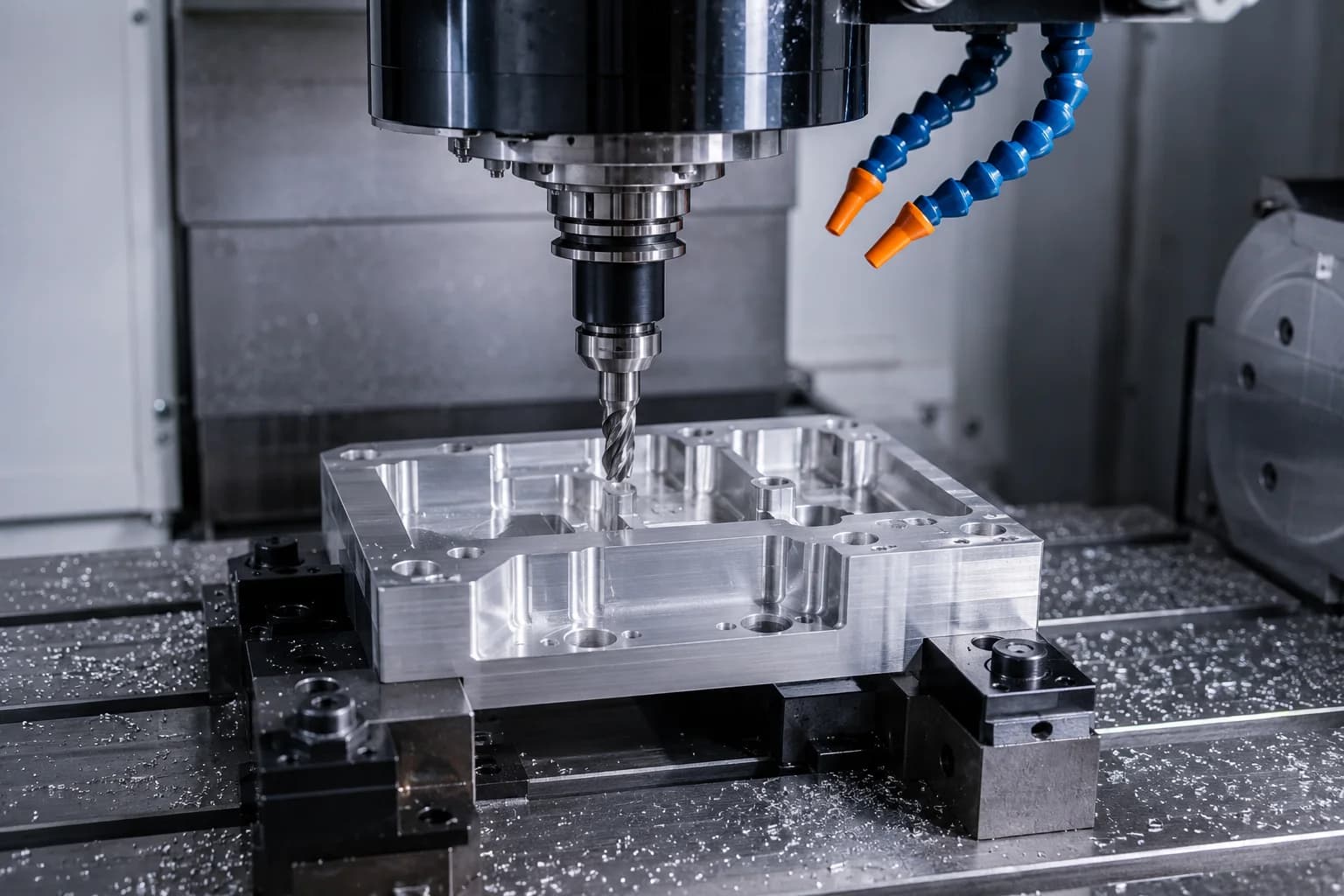
CNC milling is one of the most widely used manufacturing processes for producing prismatic parts, housings, plates, and components with complex geometry. Using a computer-controlled rotary cutting tool, material is removed from a solid workpiece to create flat faces, pockets, slots, holes, contours, and functional surfaces with high precision and repeatability.
This process is essential in industries that require components with multiple machined faces, precise assemblies, functional pockets, and consistent finishes. From functional prototypes to repeatable production, CNC milling transforms CAD models into assembly-ready parts through automated, numerically controlled operations.
At PREMSA Industries, milling is part of our CNC machining services, with capacity in Monterrey and support for projects across Mexico and North America — see CNC machining in Monterrey for local quoting. For broader CNC context, read what is CNC machining and our CNC machining design guide.
This guide explains what CNC milling is, how it works, which operations and machine types exist, compatible materials, advantages and limitations, design for manufacturability (DFM) best practices, when to choose milling vs turning, and how to prepare files to quote machined parts.
- What CNC milling is — basic process principles, material removal, and ideal geometries
- How it works — spindle, cutting tools, workholding, and the CAD → CAM → CNC flow
- Operations and machines — facing, profiling, pockets, slots, drilling, and 3-, 4-, and 5-axis machining centers
- Materials and applications — aluminum, steels, stainless steel, engineering plastics, and key industrial sectors
- DFM and limitations — internal radii, deep pockets, setups, tolerances, and tool access
- Milling vs turning — when to use each process and how to choose the best option for a part
What is CNC milling?
CNC milling is a subtractive manufacturing process in which a rotary cutting tool removes material to generate three-dimensional geometry with strong dimensional control and repeatability. During the process, end mills, drills, and other tools rotate at high speed while following programmed paths to produce surfaces, pockets, holes, slots, and complex contours.
Unlike CNC turning — where the part rotates on its axis and the tool stays relatively fixed — CNC milling relies primarily on tool rotation for cutting action. That makes it the ideal choice for prismatic components, machined plates, brackets, housings, manifolds, and parts with multiple faces or geometric features. To quote production, explore our CNC milling service.
In a conventional process, the operator manually controls feed rates, positions, and cut depths. In CNC milling, these variables are executed automatically by numerical control from programs generated in CAD/CAM software. The result is higher precision, better repeatability, and a significant reduction in errors between parts.
Because of this combination of automation and geometric flexibility, CNC milling has become one of the most important technologies in modern manufacturing for prototypes, tooling, industrial automation, and precision component production.
If a part requires multiple machined faces, pockets, holes, or complex contours, CNC milling is usually the most efficient process to manufacture it with precision and repeatability.
How does CNC milling work?
CNC milling combines rotary cutting tools, coordinated multi-axis motion, and precision workholding to transform solid material blocks into finished components. The entire process is controlled by a CNC program that tells the machine where to move, which tool to use, what speed to run, and how much material to remove at each stage.
The typical flow starts with a CAD model, continues with CAM programming where machining paths are generated, and ends with program execution on the machine. During manufacturing, the part goes through roughing, semi-finishing, and finishing operations until required dimensions, tolerances, and surface finishes are achieved.
Rotary tool vs fixed workpiece
The defining characteristic of milling is that cutting energy comes from a rotating tool. While the part is held with vises, fixtures, or specialized workholding systems, the tool spins at high speed and advances along programmed paths to remove material in a controlled way.
This setup enables machining of flat faces, pockets, holes, slots, and complex contours. Depending on part orientation and machine capability, multiple surfaces can also be accessed within the same manufacturing process.
Multi-axis motion
The most common CNC mills operate in 3 axes (X, Y, and Z), enough for a wide variety of prismatic components. As parts become more complex, additional rotary axes can be added to access more faces without constantly removing and repositioning the workpiece.
Each additional axis reduces setups, improves geometric relationships between machined surfaces, and enables more complex components with higher precision. This is especially valuable in industries where repeatability and dimensional control are critical.
- 3-axis — ideal for plates, brackets, housings, and standard prismatic parts
- 4-axis — adds a rotary axis to machine side faces with fewer reorientations
- 5-axis — orients tool and part to access complex geometry with fewer setups and better precision
From CAD to CAM toolpaths
The CNC program is not written directly from a technical drawing. The process normally starts with a CAD model imported into CAM software, where tools, machining strategies, cutting parameters, and operation sequences are selected.
Once toolpaths are defined, the programmer simulates the process to verify collisions, cycle times, and tool accessibility. Finally, the software generates the CNC code the machine will execute to manufacture the part.
CAD model quality, drawing clarity, and correct tolerance definition directly affect both cost and preparation time. To learn more about this workflow, see our CAD file to CNC machining guide.
Main components of a CNC mill
- Spindle — rotates the cutting tool at the RPM required for the material and operation
- Cutting tools — end mills, drills, reamers, taps, and special tools for different geometries
- Work table — surface where the part or fixturing system is mounted
- Workholding system — vises, plates, dedicated fixtures, or vacuum systems that keep the part stable during machining
- CNC control — interprets the program, coordinates axis motion, and controls machine functions
- Coolant system — helps control temperature, chip evacuation, and tool life
Final part precision does not depend on the machine alone. Workholding stability, correct tool selection, machining strategy, and programming quality directly influence achievable tolerances and surface finish. Even the most advanced machining center can produce poor results if the part is not held correctly or if the cutting strategy is inadequate.
CNC milling is not just about moving a tool. Final part quality depends on the combination of CAD design, CAM programming, workholding, tooling, and machining strategy.
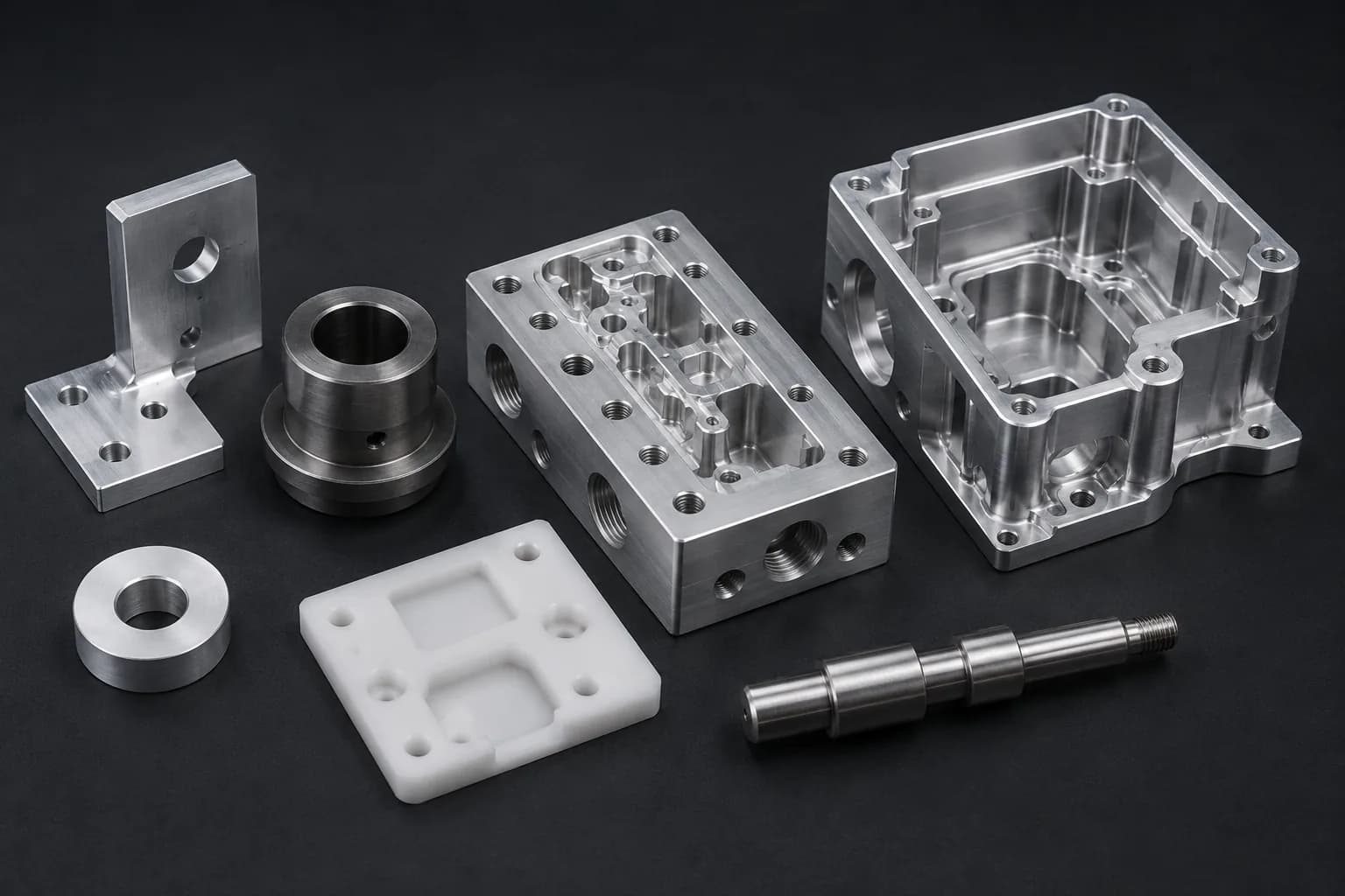
What types of parts can be made with CNC milling?
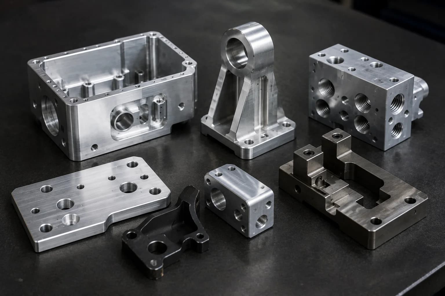
One of the biggest advantages of CNC milling is its ability to produce a huge variety of geometries. Unlike processes specialized in cylindrical or rotational parts, milling can produce components with flat faces, pockets, holes, slots, complex contours, and multiple machined surfaces in a single part.
This flexibility makes it one of the most used processes for mechanical components, tooling, automation devices, functional prototypes, and production parts in virtually every industry.
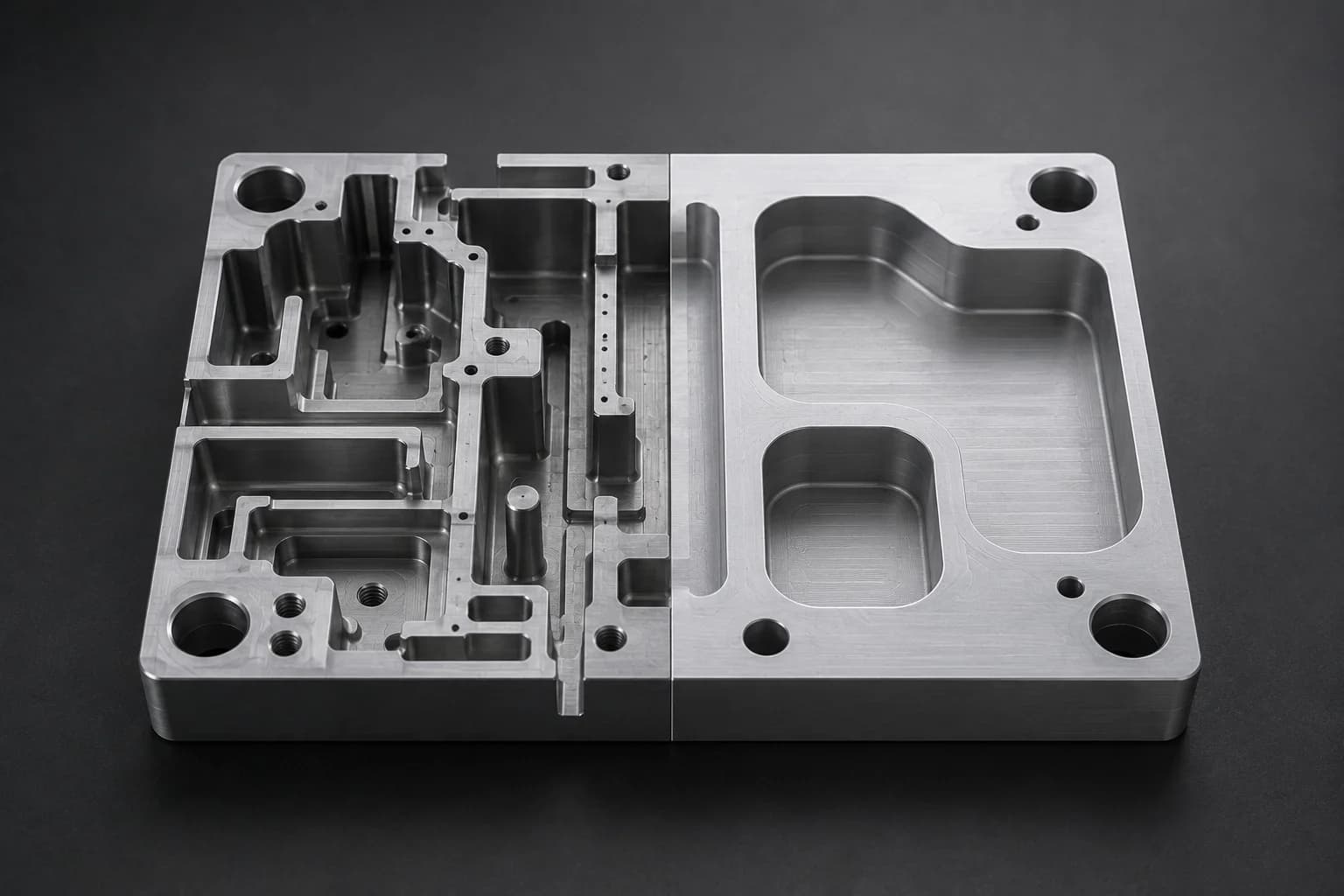
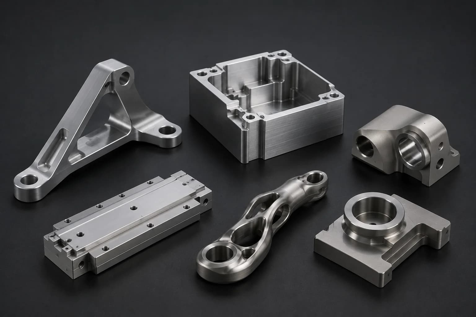
- Prismatic parts — components with flat faces, orthogonal surfaces, and rectangular or polygonal geometry
- Housings and mechanical bodies — housings, enclosures, and structures with internal cavities for assemblies or electronic components
- Machined plates — bases, adapters, mounting plates, and components with precision hole patterns
- Pocketed components — pockets and geometry designed to reduce weight or integrate specific functions
- Fixtures and tooling — workholding devices, inspection templates, and auxiliary manufacturing tools
- Functional prototypes — design validation, mechanical testing, and product development before production
- Precision production components — repeatable parts with controlled tolerances and dimensional inspection requirements
When a part requires multiple machined faces, complex pockets, precision holes, or a combination of different operations in one component, CNC milling usually becomes the primary manufacturing process.
If a part can be imagined as a solid block with material removed to create its final shape, there is a high probability it can be manufactured with CNC milling.
Common CNC milling operations
A milled part is rarely made in a single operation. In practice, a component usually passes through multiple machining stages where different tools generate surfaces, holes, pockets, and specific geometric features.
The combination of these operations transforms a material block into a finished part with required dimensions, tolerances, and finishes.
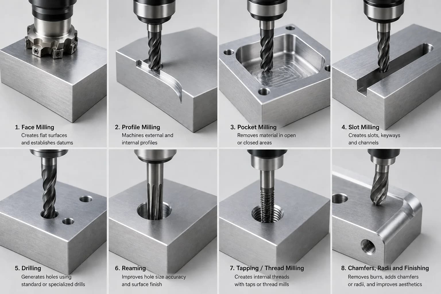
- Face milling — creating flat surfaces and dimensional references
- Profile milling — machining outer and inner profiles following part geometry
- Pocket milling — removing material in closed or open areas to create pockets and functional zones
- Slot milling — producing slots, keyways, and channels of different widths and depths
- Drilling — generating holes with standard drills or specialized tools
- Reaming — improving dimensional tolerance and surface finish in critical holes
- Threading (tapping and thread milling) — creating internal threads with taps or thread mills
- Chamfers, radii, and finishing — final operations to remove burrs, improve assembly, or meet aesthetic requirements
The process normally starts with roughing operations to remove large volumes of material, continues with semi-finishing to approach final geometry, and ends with finishing passes that achieve tight tolerances and better surface finishes. Depending on part requirements, critical holes may also need additional operations such as reaming, boring, or threading.
Final quality of a milled part depends not on a single operation, but on the correct combination of roughing, finishing, tooling, and cutting parameters.
Types of CNC milling machines
Not every part requires the same machine configuration. Geometric complexity, tolerances, production volume, and the number of faces that must be machined directly influence equipment selection.
Although many people associate advanced machining with 5-axis machines, a large share of industrial components is manufactured efficiently on 3-axis machining centers using appropriate fixturing strategies and multiple setups. The key is choosing the right technology for each project's geometry and requirements.
Vertical machining centers (VMCs)
Vertical machining centers are the most widely used CNC milling machines in industry. In this configuration, the spindle is oriented vertically over the part and can produce a wide variety of prismatic components, plates, brackets, fixtures, and housings.
Their versatility, programming ease, and relatively accessible cost make them the most common solution for prototypes and low- to medium-volume production.
Horizontal machining centers (HMCs)
Horizontal centers use a horizontally oriented spindle and are often found in higher-volume production environments. Their main advantage is natural chip evacuation by gravity, which improves process stability and reduces material buildup during machining.
Many horizontal systems also include pallet changers that allow one part to be prepared while another continues in production, significantly increasing productivity.
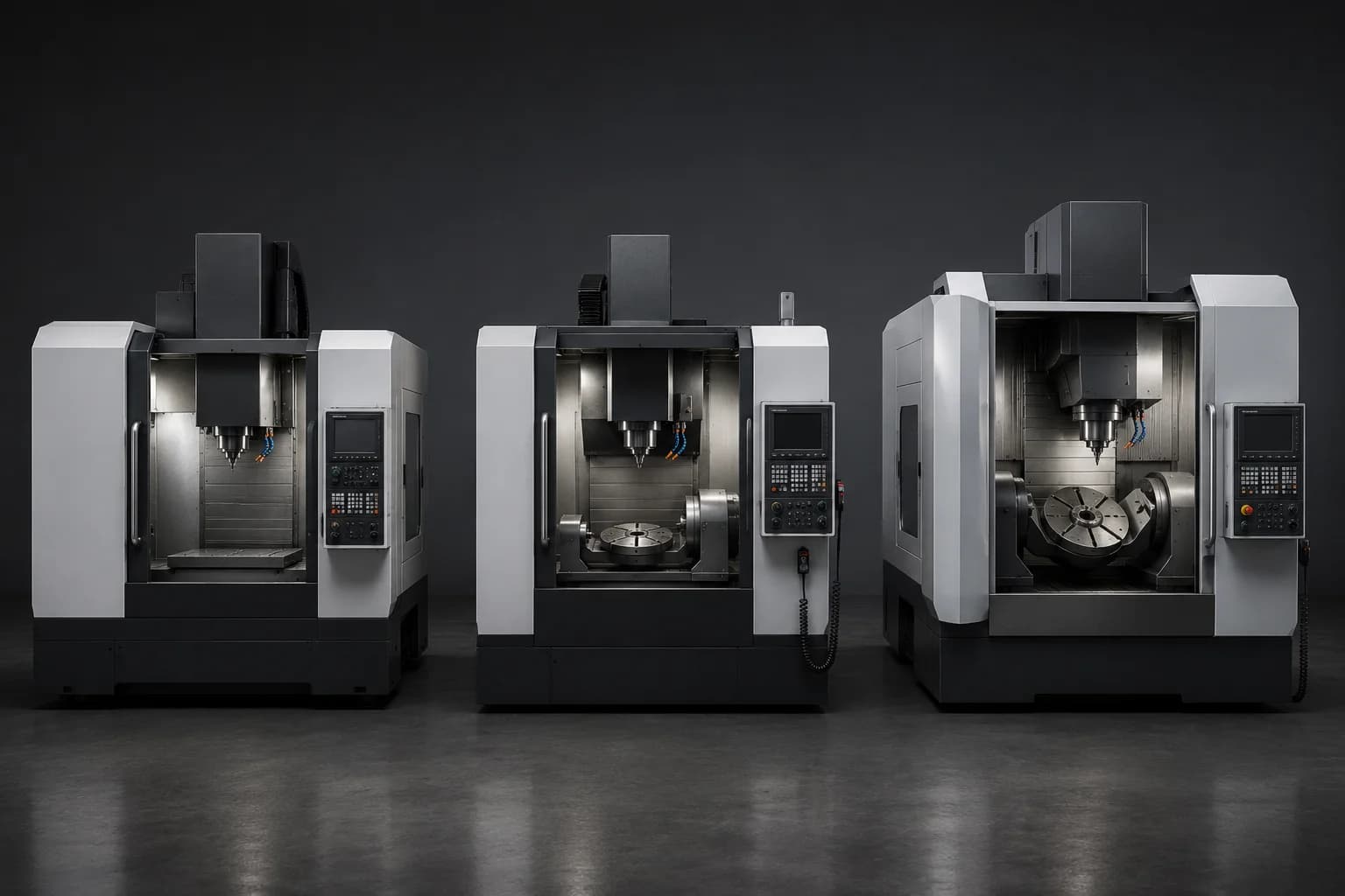
3-, 4-, and 5-axis CNC machines
- 3-axis — the most common configuration for prismatic parts, plates, brackets, and components with mainly top-side access
- 4-axis — adds a rotary axis to machine side faces with fewer part reorientations
- 5-axis — adds two rotary motions to access complex surfaces, reduce setups, and improve geometric relationships between features
Each additional axis expands the machine's geometric capability but also increases programming complexity and equipment cost. That is why a 5-axis machine is not always the most efficient solution; many parts can be manufactured economically on 3- or 4-axis equipment with the right manufacturing strategy.
Multitasking centers
Multitasking centers combine milling and turning operations in one machine. This allows parts that mix prismatic and rotational features to be produced without transferring components between different equipment.
Fewer setups improve precision between operations and can significantly reduce manufacturing time on complex components.
When a part combines turned surfaces and milled features, it may be worth evaluating mill-turn machining instead of using multiple machines and reorientations.
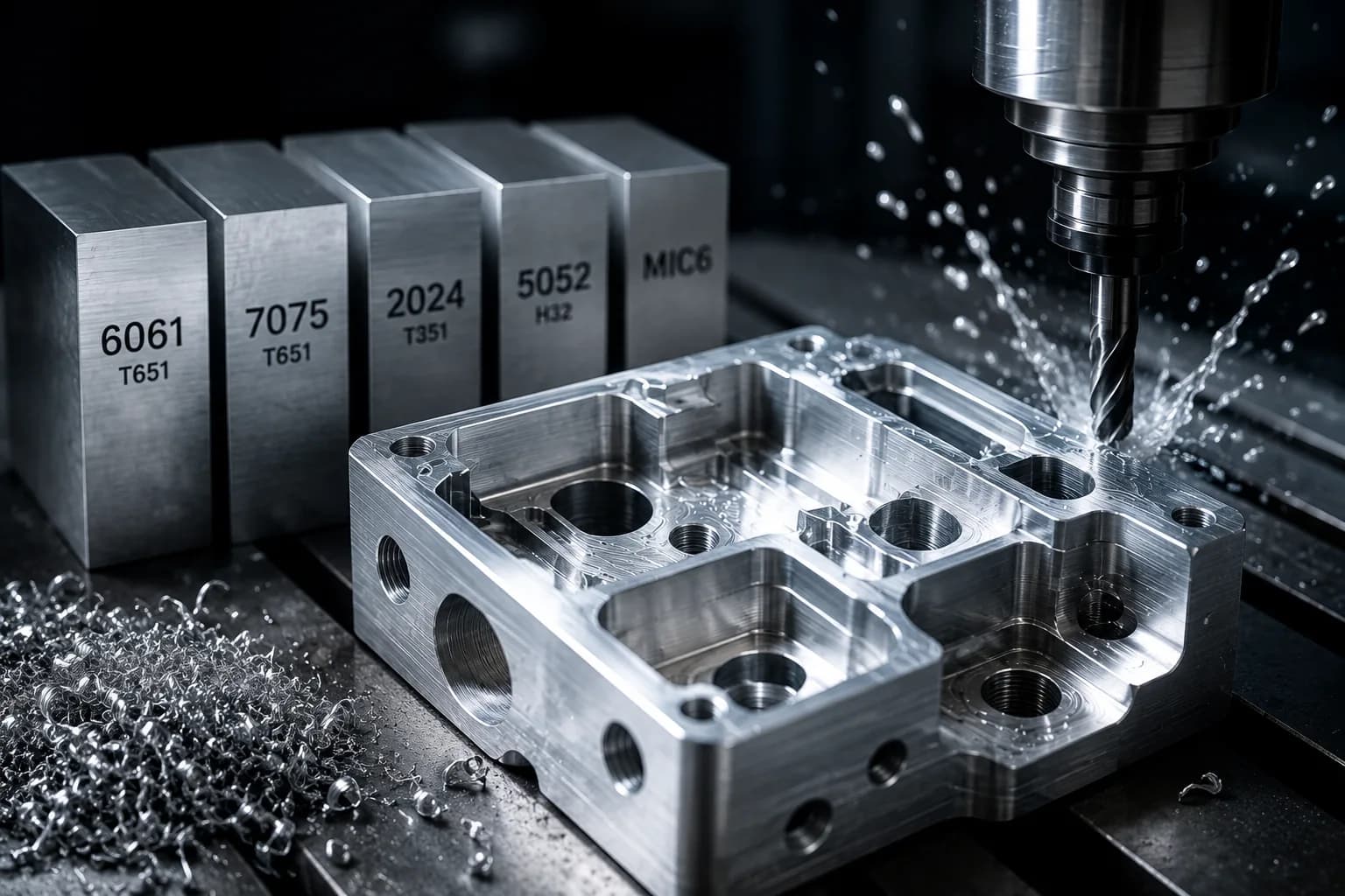
Common materials for CNC milling
One of the main advantages of CNC milling is compatibility with a wide variety of materials. From aluminum and steel to high-performance engineering plastics, the same machine can adapt to different applications through tool changes, cutting parameters, and machining strategies.
Material selection directly affects cycle time, tool wear, surface finish, dimensional stability, and final manufacturing cost. Choosing the right material is therefore one of the most important decisions during part development.
Metals
- Aluminum — excellent machinability, high strength-to-weight ratio, and one of the most used materials for prototypes and production
- Carbon steel — widely used for mechanical components, structures, tooling, and general industrial applications
- Alloy steels — offer higher mechanical properties and wear resistance for demanding applications
- Stainless steel — ideal for corrosive environments, sanitary applications, and components exposed to moisture or chemicals
- Brass and copper — materials with excellent electrical and thermal conductivity used in connectors and electrical components
- Titanium — combines high strength with low weight, although it requires more specialized machining strategies
Engineering plastics
- Nylon — good mechanical strength and low friction for moving components
- Acetal (Delrin) — excellent dimensional stability and machinability for gears, bushings, and precision components
- PEEK — high-performance polymer used in medical, chemical, and aerospace applications
- UHMW — very low-friction material ideal for guides, wear strips, and wear components
- PTFE (Teflon) — stands out for chemical resistance and non-stick properties
Beyond mechanical properties, each material presents distinct manufacturing challenges. Some allow high cutting speeds and reduced cycle times, while others require specialized tools, conservative parameters, and more careful machining strategies.
To compare specific materials, see our CNC machining materials library. To understand how material selection affects final price, also read our CNC machining material cost guide.
Advantages of CNC milling
CNC milling has become one of the most widely used technologies in modern manufacturing because it combines precision, flexibility, and repeatability in a single process. From functional prototypes to serial production, it enables complex components without dedicated molds or tooling.
Its ability to adapt quickly to design changes and produce geometries that are difficult to manufacture with conventional methods makes it an attractive solution for engineering, product development, and precision manufacturing.
- High precision — dimensional control on faces, pockets, holes, and contours with demanding industrial tolerances
- Excellent repeatability — once the program is validated, consistent parts can be produced repeatedly
- Broad material compatibility — aluminum, steels, stainless steel, titanium, brass, and engineering plastics
- Geometric flexibility — pockets, walls, holes, and multiple surfaces in one part
- Scalability — the same process works for prototypes, small lots, and repeatable production
- Integration with other processes — compatible with drilling, threading, engraving, surface finishes, and hardware installation
Because of this combination of precision and versatility, CNC milling is often the first choice for mechanical components, tooling, industrial automation, medical devices, aerospace parts, and applications where dimensional quality is a critical requirement.
Limitations of CNC milling
Although CNC milling is extremely versatile, no manufacturing process can produce every geometry without limits. Understanding its constraints helps select the right technology and design parts that are easier to manufacture, inspect, and assemble.
In many cases, the biggest cost-reduction opportunities come from designing around these limitations during the CAD stage.
- Tool-inaccessible geometry — some areas cannot be reached without 5-axis capability, special tools, or complementary processes such as EDM
- Extremely deep pockets — long tools reduce rigidity, increase vibration, and raise machining time
- Unavoidable internal radii — every internal corner retains the radius of the tool used; very small radii increase cost
- Rising costs on complex parts — multiple setups, special tools, and additional inspection increase final price
- Access constraints — tall walls, narrow spaces, and hidden geometry limit available machining strategies
Many of these limitations can be mitigated through good design for manufacturability, appropriate fixturing strategy, or use of 4- and 5-axis machines. However, understanding them during design usually has the greatest impact on cost, lead time, and manufacturing ease.
Most manufacturing problems do not appear at the machine; they start in design when geometry demands unnecessary tools, setups, or tolerances.
Design considerations for CNC milling
Much of the cost of a milled part is determined long before the machine starts cutting material. Seemingly small CAD decisions can translate into special tools, more setups, longer cycle times, or additional inspection.
Applying design for manufacturability (DFM) principles reduces cost, improves quality, and simplifies production without compromising part function.
- Design appropriate internal radii — radii compatible with standard tools reduce machining time and cost
- Avoid excessively deep pockets — high depth-to-diameter ratios force use of less rigid tools
- Use standard tools — commercial diameters simplify programming, availability, and lead times
- Reduce unnecessary setups — consolidating operations in fewer orientations improves precision and productivity
- Apply realistic tolerances — specify high precision only where it adds functional value
- Design for tool access — consider workholding, thin walls, and accessibility from early stages
In many projects, small design adjustments significantly reduce manufacturing cost without changing component performance. Larger radii, fewer orientations, shallower pockets, and well-defined tolerances often produce immediate improvements in both price and lead time.
To go deeper on these criteria, see our CNC machining design guide, our guide on how to reduce CNC part cost with simple design changes, and our CNC machining tolerances guide.
CNC milling vs CNC turning
Milling and turning are the two most important processes within CNC machining. Both remove material to produce precision components, but they use different cutting principles and are optimized for different geometric families.
The right choice depends not only on tolerance or material, but mainly on part shape. While turning excels on cylindrical, symmetric components, milling stands out when flat faces, pockets, holes, complex contours, or multiple machined surfaces are required.
| Feature | CNC Milling | CNC Turning |
|---|---|---|
| Workpiece | Generally fixed on table or fixture | Rotates on its axis in the spindle |
| Tool | Rotates (end mills, drills, and rotary tools) | Usually fixed; cuts against a rotating part |
| Ideal for | Plates, housings, brackets, and prismatic components | Shafts, bushings, connectors, adapters, and cylindrical parts |
| Geometries | Pockets, holes, multiple faces, and complex contours | Rotational geometry and cylindrical profiles |
| Typical setups | One or several depending on faces to machine | Generally one or two for rotational parts |
| Related process | CNC Milling | CNC Turning |
As a general rule, use CNC turning when the part can be described mainly by diameters and lengths. If the part requires multiple machined faces, pockets, holes in different orientations, or prismatic geometry, CNC milling is usually the better alternative.
In many modern industrial components, both processes are combined. A turned body may later need holes, flat faces, or milled slots, while a prismatic part may incorporate rotational features. In these cases, mill-turn machining or a sequence of conventional turning and milling may be appropriate.
To go deeper on the rotational process, see our guide on what is CNC turning.
The most important difference is simple: in turning the part spins; in milling the tool spins.
Industrial applications of CNC milling
Because of its ability to produce complex geometry with precision and repeatability, CNC milling is present in virtually every industry that uses mechanical components. From development prototypes to serial production, thousands of parts rely on this process daily to meet functional, dimensional, and assembly requirements.
- Automotive industry — welding fixtures, automation components, brackets, prototypes, and production-line parts
- Aerospace — structural supports, mounts, precision housings, and components with strict tolerances
- Energy — manifolds, oil & gas components, generation equipment, and control systems
- Medical devices — precision components, tooling, fixtures, and specialized equipment
- Industrial automation — plates, adapters, mechanical bases, end effectors, and integration systems
- OEM machinery — housings, machined structures, assembly components, and replacement parts
Many parts used in these sectors share similar characteristics: multiple machined faces, hole patterns, functional pockets, controlled tolerances, and need for repeatability between components. These are precisely the applications where CNC milling offers its greatest advantages over other manufacturing processes.
In the Monterrey region — an automotive, aerospace, and automation hub — milling is one of the most in-demand processes for prototypes and industrial production. For local projects, see CNC machining in Monterrey or our CNC machining in Monterrey guide.
How CNC milling affects cost and manufacturing time
The cost of a milled part depends not only on material or component size. In most projects, the factors that most affect price are machine time, geometric complexity, number of setups, and tolerance and inspection requirements.
Two parts made from the same material can have completely different costs if one requires multiple orientations, deep pockets, special tools, or significantly tighter tolerances. That is why understanding how the process works helps make better design and manufacturing decisions.
- Cycle time — deep pockets, small tools, and finishing passes increase machine hours
- Number of setups — each additional orientation implies preparation, alignment, fixturing, and inspection
- Geometric complexity — small radii, thin walls, and hard-to-reach features increase programming and machining time
- Tolerances and inspection — critical dimensions require more finishing time and dimensional validation
- Material — some materials allow high speeds while others generate greater tool wear
- Quantity — setup costs are spread more effectively as production volume increases
Often, small design changes generate significant cost reductions. Larger internal radii, fewer machining orientations, or tolerances applied only where they add functional value usually have more impact than trying to negotiate price after quoting.
To go deeper on these factors, see what affects CNC machined part cost most, how to reduce CNC part cost with simple design changes, and our CNC machining cost guide.
In CNC milling, machine time usually has more impact on final cost than the amount of material removed.
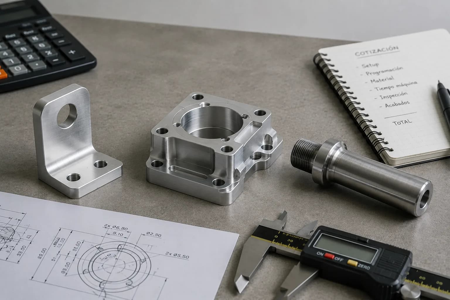
How to prepare files to quote CNC milling
An accurate quote starts with clear technical information. When the supplier receives a complete package from the start, it can evaluate manufacturability, select machining strategies, and estimate manufacturing time more accurately.
Beyond speeding up quoting, proper documentation reduces follow-up clarifications, avoids interpretation errors, and facilitates DFM review before releasing production.
- 3D STEP model — primary reference to review geometry, tool access, and machining time
- 2D PDF drawing — critical tolerances, threads, finishes, special notes, and engineering revisions
- Material and quantity — complete material specification and required volume
- Required finishes — anodizing, paint, passivation, zinc plating, or other post treatments
- Inspection requirements — dimensional reports, FAI, certificates, or special documentation
- Target date — helps evaluate priorities and realistic manufacturing lead times
If this is your first time requesting machined parts, also see how to get CNC parts made and CAD file to CNC machining to understand the full flow from design to production.
How PREMSA Industries manufactures milled parts
At PREMSA Industries we manufacture milled components for prototypes, low-volume runs, and repeatable production with a focus on manufacturability, dimensional precision, and process consistency.
Before releasing a manufacturing order, we review geometry, material, tolerances, and functional requirements to identify manufacturing risks and optimization opportunities that can reduce cost or lead time.
- Functional prototypes — fast validation of design, assembly, and performance
- Low-volume production — small series without high MOQ requirements
- Repeatable production — consistent manufacturing for projects with recurring demand
- Integrated DFM review — manufacturability analysis from the quoting stage
- Dimensional inspection — validation of critical features before releasing production
- Technical support — feedback on design, tolerances, and manufacturing strategy
Within our CNC machining services, we integrate CNC milling, CNC turning, and mill-turn machining, enabling everything from simple prismatic parts to components that combine rotational and milled features in one project. For teams in Nuevo León, our CNC machining in Monterrey page summarizes capabilities, materials, and online quoting.
Request a quote by sending your STEP model and technical drawing, or contact us for projects with special material, tolerance, or inspection requirements.
Frequently asked questions about CNC milling
Practical answers for engineering, manufacturing, and purchasing on precision, materials, cost, and milled part production.
- What is the difference between CNC milling and CNC turning?
- The main difference is which element generates cutting motion. In CNC milling the tool rotates while the part stays clamped; in CNC turning the part rotates on its axis while the tool advances. Milling is ideal for plates, housings, and prismatic parts; turning is ideal for shafts, bushings, and cylindrical components.
- How precise can CNC milling be?
- Precision depends on the machine, material, machining strategy, workholding, and inspection. Many industrial applications combine general tolerances with clearly identified critical dimensions to control cost and manufacturability.
- What materials can be machined with CNC milling?
- CNC milling can be used with aluminum, carbon steel, alloy steels, stainless steel, titanium, copper, brass, and many engineering plastics such as nylon, acetal, PEEK, UHMW, and PTFE.
- What is the difference between 3-, 4-, and 5-axis CNC machines?
- 3-axis machines are suitable for most prismatic components. 4-axis machines add rotation to access more faces without repositioning the part. 5-axis machines orient the tool toward complex surfaces, reducing setups and expanding geometric possibilities.
- Is CNC milling suitable for prototypes and production?
- Yes. It is one of the few processes that works efficiently for both one-off prototypes and repeatable production. As quantity increases, programming and setup costs are spread across more parts.
- How does design affect CNC milling cost?
- Small internal radii, deep pockets, multiple setups, and unnecessarily tight tolerances often significantly increase machine time and manufacturing cost. Applying DFM principles from CAD can generate important savings.
- What files are needed to quote a milled part?
- Ideally provide a STEP model, PDF drawing with tolerances and critical notes, material specification, required quantity, finishes, and target date. The more complete the information, the more accurate the quote.
- What factors most influence the cost of a milled part?
- The most important factors are usually machine time, number of setups, geometric complexity, tolerances, material, and required inspection. In many cases machining time has more impact than raw material cost.
- When is CNC milling preferable to 3D printing?
- CNC milling is usually preferable when real production materials, tighter tolerances, better mechanical properties, or more consistent surface finishes are required than those typically achieved with 3D printing.
- What is the maximum part size that can be manufactured with CNC milling?
- It depends on each machining center's capacity. Maximum dimensions are limited by machine travel, part weight, and fixturing strategy. The best way to validate feasibility is to share the CAD model for review.
The main difference is which element generates cutting motion. In CNC milling the tool rotates while the part stays clamped; in CNC turning the part rotates on its axis while the tool advances. Milling is ideal for plates, housings, and prismatic parts; turning is ideal for shafts, bushings, and cylindrical components.
Precision depends on the machine, material, machining strategy, workholding, and inspection. Many industrial applications combine general tolerances with clearly identified critical dimensions to control cost and manufacturability.
CNC milling can be used with aluminum, carbon steel, alloy steels, stainless steel, titanium, copper, brass, and many engineering plastics such as nylon, acetal, PEEK, UHMW, and PTFE.
3-axis machines are suitable for most prismatic components. 4-axis machines add rotation to access more faces without repositioning the part. 5-axis machines orient the tool toward complex surfaces, reducing setups and expanding geometric possibilities.
Yes. It is one of the few processes that works efficiently for both one-off prototypes and repeatable production. As quantity increases, programming and setup costs are spread across more parts.
Small internal radii, deep pockets, multiple setups, and unnecessarily tight tolerances often significantly increase machine time and manufacturing cost. Applying DFM principles from CAD can generate important savings.
Ideally provide a STEP model, PDF drawing with tolerances and critical notes, material specification, required quantity, finishes, and target date. The more complete the information, the more accurate the quote.
The most important factors are usually machine time, number of setups, geometric complexity, tolerances, material, and required inspection. In many cases machining time has more impact than raw material cost.
CNC milling is usually preferable when real production materials, tighter tolerances, better mechanical properties, or more consistent surface finishes are required than those typically achieved with 3D printing.
It depends on each machining center's capacity. Maximum dimensions are limited by machine travel, part weight, and fixturing strategy. The best way to validate feasibility is to share the CAD model for review.
Related resources
If you are defining scope, material, or manufacturability for a milled part, these resources complement this guide without duplicating its focus:
- PREMSA Industries home — on-demand manufacturing platform, quoting, and integrated capabilities.
- CNC milling service — quoting and production of prismatic parts.
- CNC machining services — milling, turning, mill-turn, and complementary processes.
- CNC machining design guide — DFM rules before the RFQ.
- What is CNC machining — overview of processes and machine types.
- What is CNC turning — when the rotational process makes sense.
- CNC machining in Monterrey — local capabilities and quoting.
- CAD file to CNC machining — prepare STEP files and drawings to quote.
- CNC machining tolerances — specify precision realistically.
Conclusion: CNC milling as a foundation of modern manufacturing
CNC milling is one of the most versatile, precise, and widely used manufacturing processes in modern industry. Its ability to produce complex components from a wide variety of materials makes it a fundamental technology for prototypes, automation, tooling, and industrial production.
From simple machined plates to complex housings with multiple surfaces, CNC milling transforms CAD models into functional parts with high levels of repeatability and dimensional control.
Understanding how the process works, which machine types exist, which materials are compatible, and how design affects cost and manufacturability helps engineering and purchasing teams make better decisions.
In many projects, factors such as internal radii, pocket depth, tolerances, and number of setups influence the final outcome more than material itself. That is why applying design for manufacturability principles from the start usually generates significant benefits in cost, lead time, and production ease.
At PREMSA Industries we manufacture components through CNC milling for prototypes, low volume, and repeatable production, integrating DFM review, technical support, and dimensional inspection to help customers manufacture parts with greater confidence.
Request a quote by sending your CAD model, explore CNC machining in Monterrey if you need local manufacturing, or read our CNC machining design guide and what is CNC machining to go deeper into the CNC ecosystem.

Written by
Adrian Cavazos and the PREMSA Engineering Team
Adrian Cavazos, founder of PREMSA Industries, leads a manufacturing engineering team specialized in CNC machining, metal fabrication, and production-ready solutions. The team works closely with customers to optimize designs, improve manufacturability (DFM), and ensure reliable, scalable production from prototypes through volume manufacturing.