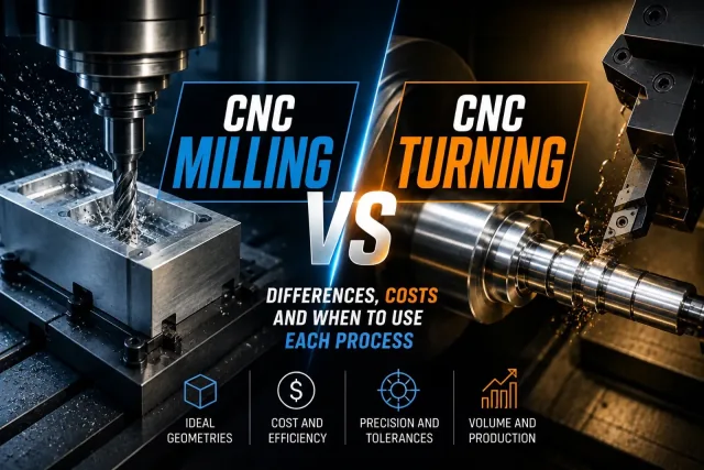
Many people use CNC machining as a catch-all term for any part made on a numerically controlled machine. In industrial practice, however, CNC milling and CNC turning are the two most common processes — and each is optimized for very different geometries, cycle times, and cost structures.
Choosing the wrong process upfront can increase cost per part, extend manufacturing lead time, and add unnecessary complexity in setups, CAM programming, and inspection. Comparing milling and turning is not academic: it is an engineering decision that directly affects manufacturability, delivery time, and project economics.
At PREMSA Industries we integrate CNC milling, CNC turning, and CNC mill-turn for prototypes, low-volume runs, and repeatable production. For background, see what is CNC machining, what is CNC milling, and what is CNC turning.
- What CNC milling is — cutting principle, ideal geometries, and process strengths
- What CNC turning is — how lathes work, typical parts, and where turning wins
- Key differences — comparison table covering motion, cost, precision, and volume
- Best-fit parts for each process — industrial milling and turning examples
- Cost and process selection — when each technology is usually more economical
- Hybrid processes — mill-turn, live tooling, and secondary operations
- DFM and practical cases — how to decide from design with real examples
What Is CNC Milling?
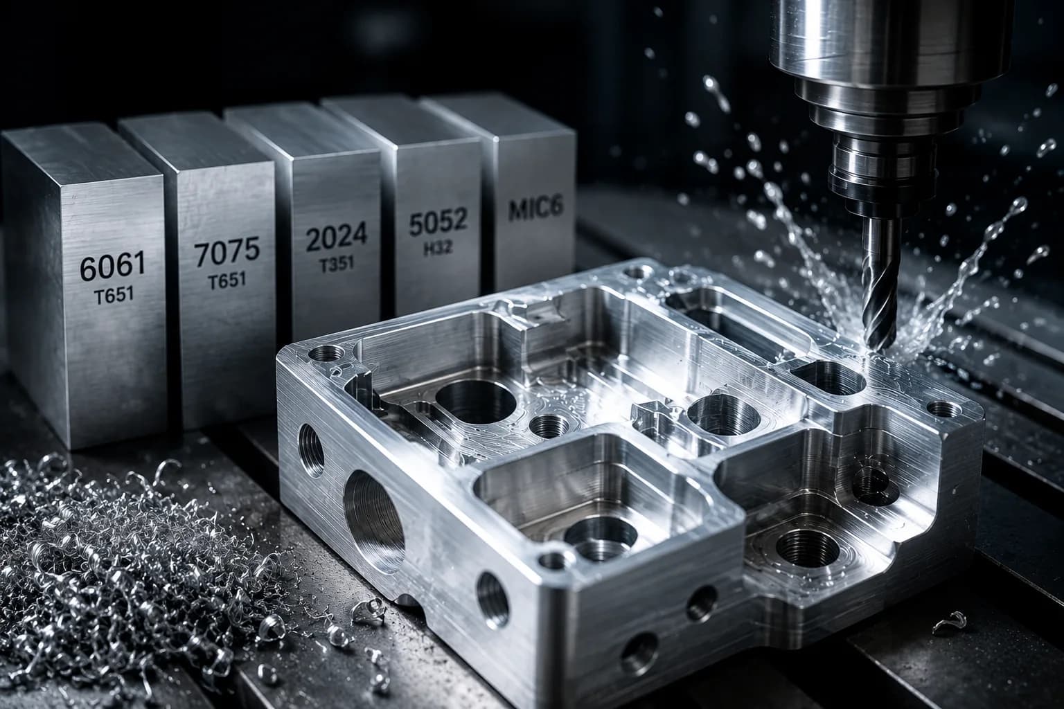
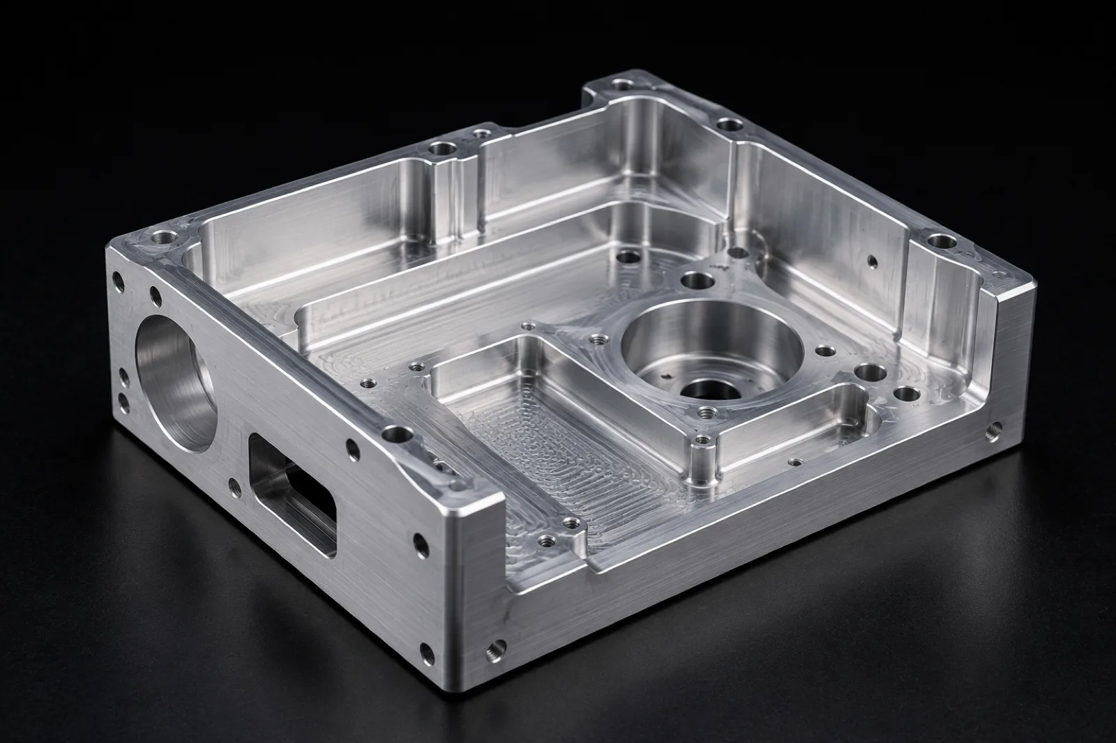
CNC milling is a subtractive manufacturing process in which a rotary cutting tool removes material from a fixed workpiece to create flat faces, pockets, holes, contours, and three-dimensional surfaces. It is the backbone of prismatic part production across automation, robotics, medical devices, aerospace, and general industrial manufacturing.
For operations, 3/4/5-axis machines, materials, and milling-specific DFM, see the full guide on what is CNC milling.
How CNC milling works
- The tool spins — end mills, drills, and indexable cutters rotate at high speed to generate the cut.
- The part stays fixed — held in vises, fixtures, or vacuum systems while the tool moves.
- Multi-axis motion — the machine coordinates X, Y, and Z (plus rotary axes on 4- or 5-axis centers) to reach different faces and geometries.
Ideal geometries for CNC milling
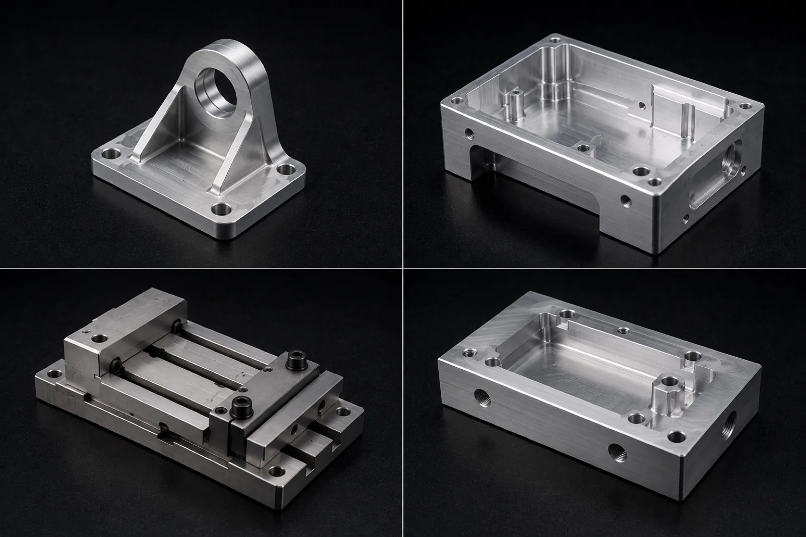
- Plates — bases, covers, panels, and machined surfaces with holes and features.
- Brackets — structural supports with multiple faces and mounting interfaces.
- Housings — enclosures with internal cavities, walls, and assembly features.
- Manifolds — fluid distributors with channels, ports, and complex internal geometry.
- Prismatic components — non-rotational parts with several functional machined faces.
Advantages of CNC milling
- Complex geometries — contours, reliefs, and transitions between surfaces.
- Cavities — pockets, housings, and functional internal volumes.
- Pockets — slots, pockets, and relief areas with dimensional control.
- 3D surfaces — curved profiles, contact surfaces, and functional finishes.
- Multiple faces — access to different orientations in one setup or controlled reorientations.
What Is CNC Turning?
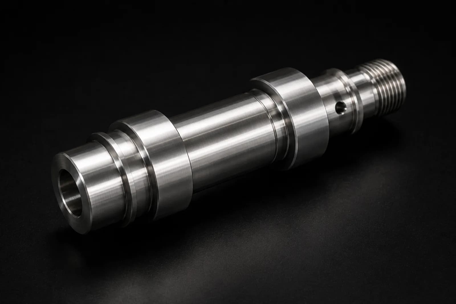
CNC turning is a process in which the workpiece spins on its axis while a cutting tool removes material to produce diameters, faces, grooves, threads, and rotational geometry. It is especially efficient when part function depends on concentricity, dimensional fit, and repeatability across a batch.
For operations, tolerances, materials, and lathe design best practices, see what is CNC turning.
How CNC turning works
- The part spins — the spindle rotates the material at high speed while the tool advances.
- The tool stays fixed — turning inserts, boring bars, and grooving tools index on the turret.
- Motion mainly on X and Z — cutting occurs in the radial and longitudinal plane, ideal for cylindrical geometry.
Ideal geometries for CNC turning
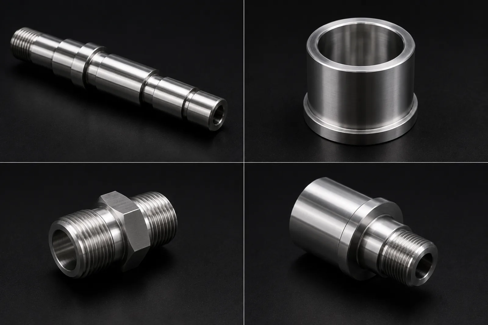
- Shafts — stepped shafts, spigots, and drivetrain components.
- Bushings — sleeves and cylindrical housings with fit tolerances.
- Spacers — bushings, standoffs, and guide elements.
- Adapters — mechanical connectors with diameters, shoulders, and threads.
- Connectors — nipples, fittings, and hydraulic or pneumatic interface parts.
Advantages of CNC turning
- Very high productivity — fast cycles on rotational geometry with few setups.
- Excellent concentricity — coaxial diameters and consistent radial relationships.
- Lower cost on cylindrical parts — leverages commercial bar and tube stock with minimal material removal.
Differences Between CNC Milling and CNC Turning
Although both processes remove material in a controlled way and can hold tight tolerances, their cutting mechanics, ideal geometry, and manufacturing economics differ. The table below summarizes the most relevant differences for engineering, purchasing, and product design.
| Characteristic | CNC Milling | CNC Turning |
|---|---|---|
| Primary motion | Rotating tool; fixed part | Rotating part; fixed tool |
| Ideal geometry | Prismatic, multi-face, with pockets | Cylindrical and rotational |
| Typical form | Plates, brackets, housings, manifolds | Shafts, bushings, adapters, connectors |
| Geometric complexity | High on 3D surfaces, pockets, and multiple faces | High on stepped profiles, threads, and coaxial grooves |
| Productivity | Varies with setups and number of faces | Very high on repetitive cylindrical parts |
| Cost per part | Often more efficient on non-symmetric geometry | Often more economical on rotational components |
| Precision | Excellent flatness, parallelism, and face-to-face relationships | Excellent concentricity, roundness, and diameters |
| Compatible materials | Aluminum, steels, stainless, brass, titanium, engineering plastics | Aluminum, steels, stainless, brass, titanium, engineering plastics |
| Recommended volume | Prototypes, low volume, and repeat production with prismatic geometry | Prototypes, low volume, and repeat runs of cylindrical parts |
There is no universally better CNC process — only the right process for the dominant geometry, available stock, and production volume.
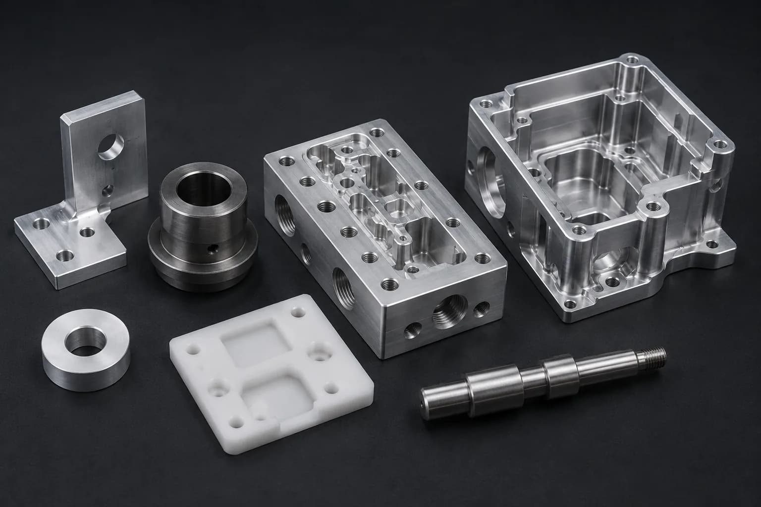
What Types of Parts Are Best Made with CNC Milling?
Prismatic components
When a part is defined by flat faces, angles, and mounting interfaces in different orientations, milling is usually the most direct path. Blocks, bases, and mechanical supports fit naturally on 3-, 4-, or 5-axis machining centers.
Parts with multiple machined faces
Brackets, fixtures, and adapters with holes, ribs, and contact surfaces on several faces benefit from multi-face milling access. Each additional setup increases cost, so design should minimize unnecessary reorientations.
Components with internal cavities
Housings and manifolds with internal pockets, channels, and thin walls require rotary tools with roughing and finishing strategies. Milling controls pocket depth, internal radii, and surface finish in functional zones.
Complex 3D geometries
Curved surfaces, reliefs, and transitions between flats and radii are more natural on a mill — especially with 4- or 5-axis machines. When aesthetics, fluid flow, or mechanical contact depend on non-cylindrical surfaces, milling leads.
What Types of Parts Are Best Made with CNC Turning?
Shafts
Shafts with stepped diameters, shoulders, spigots, and bearing zones are produced with high repeatability on a CNC lathe. Continuous rotation enables short cycles and strong concentricity control.
Bushings
Bushings, sleeves, and cylindrical spacers — with critical inner and outer diameters — are natural turning candidates. A single setup can combine OD turning, ID boring, and finishing.
Spacers
Standoffs and stack-up elements with controlled length and diameter are efficiently produced from bar or tube stock, reducing scrap and cycle time.
Threaded adapters
Nipples, fittings, and adapters with threads, shoulders, and sealing diameters are made on a lathe with integrated threading operations. For hydraulic or pneumatic connections, lathe concentricity is a direct advantage.
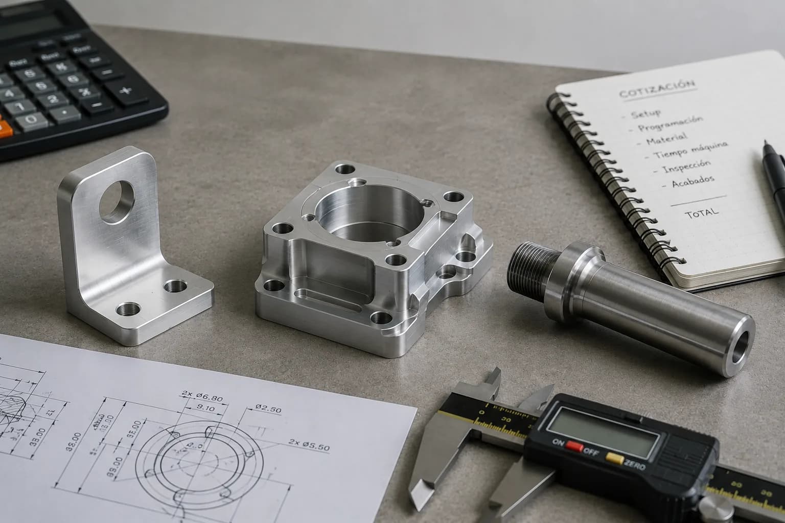
Which Is More Economical?
This is one of the most common questions in engineering and purchasing — and the honest answer is: it depends on geometry, stock, and number of operations. Neither milling nor turning is universally cheaper; each process is economical when the part is designed to leverage its strengths.
To understand what moves price the most, read what affects CNC machined part cost most and how to reduce CNC machining cost through design.
When CNC turning is usually more economical
- Cylindrical geometry — the part is machined from bar or tube with minimal material removal.
- Repeat production — short cycles and standardized setups amortize fixed programming cost.
- Higher quantities — low cycle time per part drives unit cost down quickly across runs.
When CNC milling is usually more economical
- Prismatic geometry — commercial plate and block stock is natural feedstock for machining centers.
- Multiple features — holes, pockets, contours, and surfaces on different faces within one process family.
- Non-symmetric parts — forcing prismatic geometry on a lathe requires costly secondary operations.
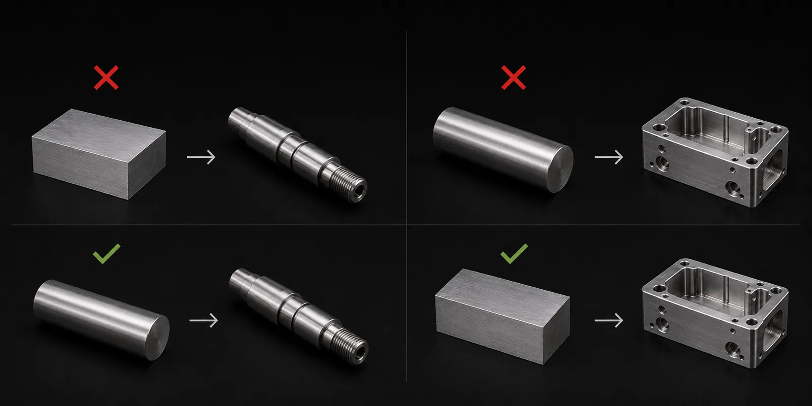
How choosing the wrong process increases cost
A common mistake is machining a part with the wrong process and paying for wasted material, extra setups, and extended cycle time. Two frequent examples:
- Shaft made from plate — a cylindrical shaft cut from a prismatic block requires removing most of the volume by milling when bar stock on a lathe would suffice.
- Block made from round bar — a bracket or housing started from cylindrical stock forces initial turning plus secondary milling to create flat faces and pockets.
Can Milling and Turning Be Combined on the Same Part?
Yes — and in modern manufacturing this is increasingly common. Many parts combine cylindrical geometry with flat faces, radial holes, or pockets that a single process cannot resolve efficiently. This is where multitask machines and secondary operations deliver real value.
Multitask machines and live-tool lathes
Lathes with live tooling and mill-turn machines integrate milling and turning in one setup. That reduces reorientations, improves relationships between coaxial and flat features, and lowers stack-up error risk between operations.
At PREMSA Industries we offer CNC mill-turn for parts that need both operation families without transferring between machines.
Common secondary operations
- Flats — milled flat faces on cylindrical parts for wrench engagement or mounting.
- Radial holes — cross holes in shafts and adapters.
- Threads — axial and radial threads on lathe or mill depending on tool access.
- Grooves — keyways, grooves, and functional channels on rotational parts.
When combining both processes makes sense
Combine milling and turning when the part has hybrid geometry — for example, a cylindrical adapter with flats, cross holes, and a flat mounting face. In these cases, an integrated mill-turn approach or a planned turning + secondary milling sequence is usually more economical than forcing everything through one process.
How to Choose the Right Process from the Design Stage
The best process decision is made before releasing the drawing — not after a quote delivers surprises. Design for manufacturability (DFM) aligns CAD geometry with real processes, commercial stock, and shop capabilities.
Design around dominant geometry
Identify whether the part is primarily cylindrical or primarily prismatic. If more than 70% of function depends on coaxial diameters, the lathe is likely the base process. If the part is defined by faces, pockets, and multi-face contours, milling is the starting point.
Leverage commercial stock
Selecting round bar, tube, plate, or block stock close to final geometry reduces scrap and cycle time. Designs that require non-standard stock or expensive preforms impact price and lead time from day one.
Reduce unnecessary operations
Every setup, machine transfer, and secondary operation adds fixed cost and dimensional variation. Consolidating features in the same orientation, avoiding tighter tolerances than function requires, and simplifying tool access are design decisions with direct manufacturability impact.
Consult manufacturing before releasing the design
An early review with the manufacturing team can show that a small geometry change — a larger internal radius, a more generous wall thickness, or a more accessible datum — significantly reduces cost without affecting function.
Recommended resources:
- CNC machining design guide — DFM principles for milling, turning, and combined processes.
- How to reduce CNC machining cost through design — geometric optimization before quoting.
- What affects CNC machined part cost most — technical factors that move price.
Practical Examples
The examples below show how dominant geometry and functional requirements determine the most efficient process. Each case reflects common scenarios in prototype work, industrial automation, and low-volume production.
Example 1: Hydraulic shaft
A hydraulic shaft with stepped diameters, sealing shoulders, grooves, and a threaded end is predominantly cylindrical. Concentricity between diameters is critical for seal performance.
Result: CNC turning — machined from bar with turning, grooving, and threading in one setup or a short lathe sequence.
Example 2: Aluminum bracket
A mounting bracket with a flat base, holes on three faces, ribs, and a pocket for a sensor is clearly prismatic. It requires access to multiple orientations.
Result: CNC milling — machined from aluminum plate or block on a 3- or 4-axis machining center.
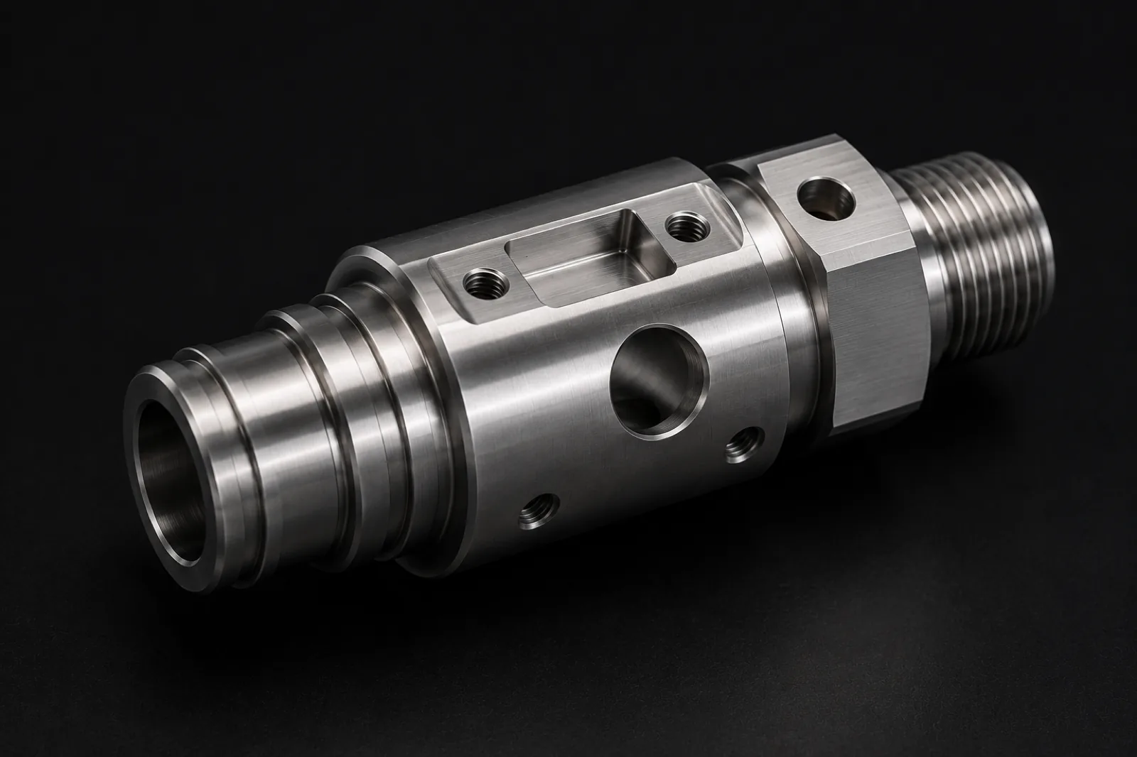
Example 3: Adapter with flats and cross holes
A cylindrical adapter with a threaded OD, two wrench flats, cross holes, and a flat contact face combines rotational geometry and milled features.
Result: Turning + live tooling — OD turning and threading on the lathe, with flats and radial holes via live tooling or mill-turn in the same setup.
Conclusion: There Is No Better Process — Only the Right One
CNC milling and CNC turning do not compete with each other — they complement each other. Each process is optimized for different geometry families, and modern manufacturing often combines both in hybrid parts or multitask machines.
Choosing correctly from the design stage reduces cost, shortens lead time, and avoids rework in programming, setups, and inspection. Consulting manufacturing early — before freezing the drawing — is one of the highest-return investments in any CNC project.
Request a quote with STEP files and specifications to receive manufacturing recommendations before production starts. At PREMSA Industries we review geometry, material, tolerances, and volume to recommend milling, turning, or a combined approach with the lowest cost and risk.
Frequently asked questions about CNC milling vs CNC turning
Direct answers for engineers, designers, and purchasing teams choosing the right CNC process.
- What is the main difference between CNC milling and CNC turning?
- In milling, the tool spins while the part stays fixed; in turning, the part spins and the tool performs the cut. That difference defines which geometries are natural for each process.
- What parts are best for CNC turning?
- Shafts, bushings, adapters, connectors, spacers, and any component with predominantly cylindrical geometry. See what is CNC turning for more detail.
- What parts are best for CNC milling?
- Brackets, plates, housings, manifolds, fixtures, and prismatic parts with multiple machined faces. Read what is CNC milling for operations and milling-specific DFM.
- Is CNC turning cheaper than CNC milling?
- Not always. Turning is usually more economical for cylindrical parts from bar stock, while milling is usually more efficient for prismatic geometry with multiple features. See what affects CNC machined part cost.
- Can one part require both CNC milling and turning?
- Yes. Many modern parts combine cylindrical and prismatic features, so they may need both processes or production on CNC mill-turn machines with live tooling.
- Which CNC process offers higher precision?
- Both can hold very tight tolerances. The choice depends more on part geometry and functional requirements — concentricity on a lathe, flatness and face relationships on a mill — than on the process itself.
- How do I know if my part should be milled or turned?
- Identify the dominant geometry. Primarily cylindrical parts are usually lathe candidates; prismatic parts or those with multiple machined faces are normally milled. An early DFM review confirms the best path.
In milling, the tool spins while the part stays fixed; in turning, the part spins and the tool performs the cut. That difference defines which geometries are natural for each process.
Shafts, bushings, adapters, connectors, spacers, and any component with predominantly cylindrical geometry. See what is CNC turning for more detail.
Brackets, plates, housings, manifolds, fixtures, and prismatic parts with multiple machined faces. Read what is CNC milling for operations and milling-specific DFM.
Not always. Turning is usually more economical for cylindrical parts from bar stock, while milling is usually more efficient for prismatic geometry with multiple features. See what affects CNC machined part cost.
Yes. Many modern parts combine cylindrical and prismatic features, so they may need both processes or production on CNC mill-turn machines with live tooling.
Both can hold very tight tolerances. The choice depends more on part geometry and functional requirements — concentricity on a lathe, flatness and face relationships on a mill — than on the process itself.
Identify the dominant geometry. Primarily cylindrical parts are usually lathe candidates; prismatic parts or those with multiple machined faces are normally milled. An early DFM review confirms the best path.

Written by
Adrian Cavazos and the PREMSA Engineering Team
Adrian Cavazos, founder of PREMSA Industries, leads a manufacturing engineering team specialized in CNC machining, metal fabrication, and production-ready solutions. The team works closely with customers to optimize designs, improve manufacturability (DFM), and deliver reliable, scalable production from prototypes through volume manufacturing.