If you need a part made, the challenge is usually not the design—it’s knowing how to move from a CAD file to a finished component without delays, miscommunication, or unnecessary cost. CNC machining services are one of the most reliable ways to manufacture precise, production-ready parts. But to get consistent results, it’s important to understand how the process works from the customer side.
This guide breaks down exactly how to get CNC parts made—from preparing your files and defining specifications to submitting a quote and moving into production. Leveraging our strategic manufacturing base in Mexico, PREMSA provides high-precision solutions and streamlined global logistics to deliver quality components to customers worldwide.
Six steps to get CNC parts made
- Design your part with manufacturable CAD, DFM principles, and required specifications.
- Choose the right process — CNC machining, 3D printing, or sheet metal fabrication.
- Select material and surface finish suited to function and environment.
- Define tolerances and specs only where function requires tight limits.
- Prepare quote-ready files (STEP + drawing when needed).
- Submit your quote and move into engineering review and production.
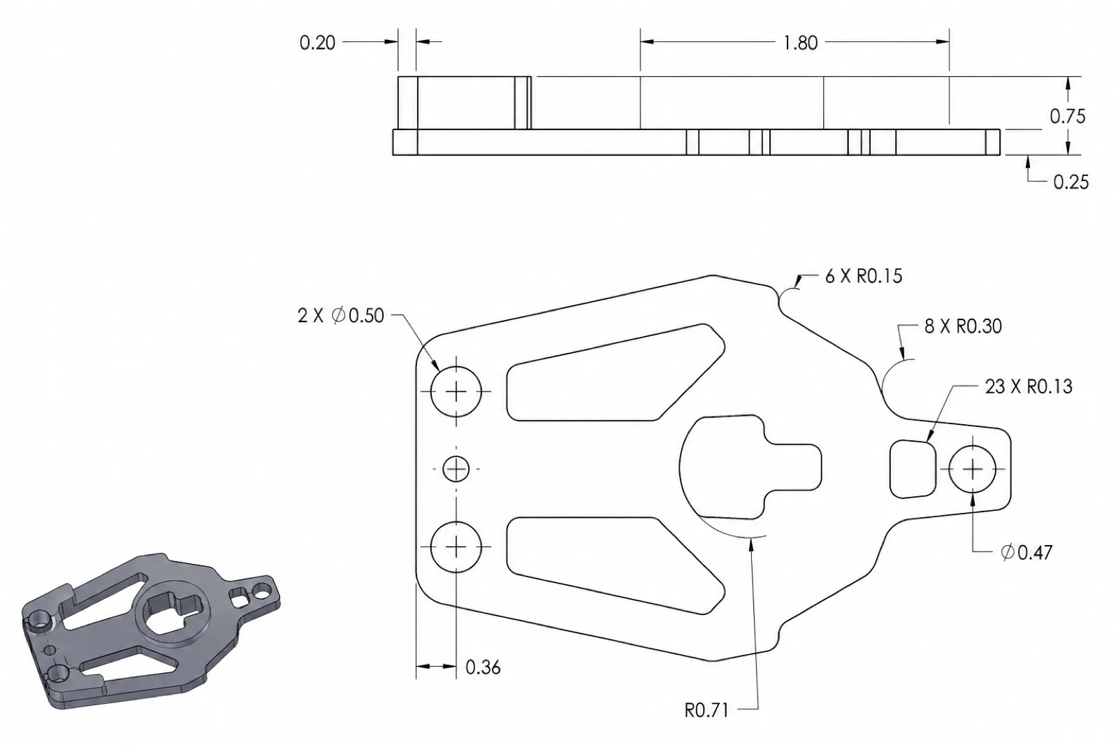
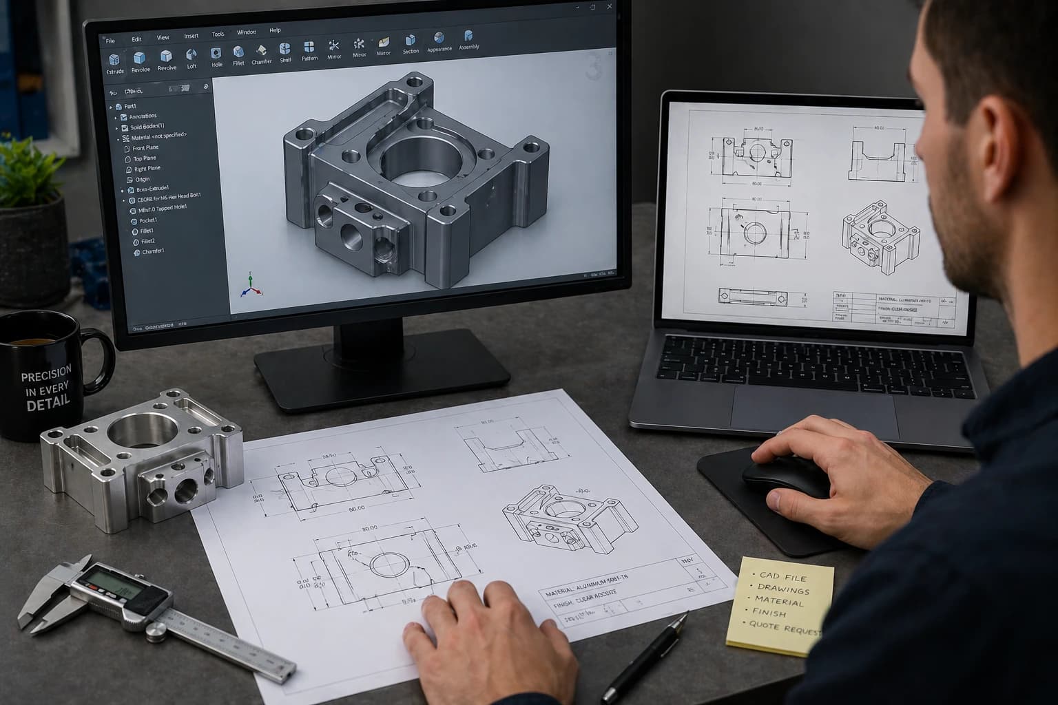
Step 1: Design Your Part (CAD & Requirements)
Every CNC project starts with a digital design, but what matters is not just having a CAD file—it’s having a design that can actually be manufactured efficiently. Many issues in machining don’t come from the machine itself, but from designs that don’t consider how tools will interact with the material.
In most cases, you’ll need a 3D CAD file such as STEP or STL, which defines the geometry of the part. While 2D drawings are optional, they become important when you need to communicate critical details such as tolerances, threads, or surface finishes. A clear and complete definition of the part reduces back-and-forth during quoting and avoids delays once production begins.
When working with CNC machining services, the quality of your design directly impacts lead time, cost, and final part accuracy. A clean model with proper dimensions allows engineers to evaluate manufacturability quickly and generate an accurate quote without unnecessary revisions.
However, having a CAD file is only part of the process. The design must follow basic Design for Manufacturability (DFM) principles to ensure it can be machined without complications. Features such as sharp internal corners, extremely thin walls, or deep narrow pockets can increase machining time, require special tooling, or even make the part impossible to produce as designed.
A well-thought-out design balances functionality with manufacturability. In many cases, small adjustments—like increasing a radius, relaxing a tolerance, or simplifying a feature—can significantly reduce cost and improve production efficiency without affecting performance.
Key Design Considerations
- Avoid extremely thin walls that may deform or require specialized tooling
- Use internal radii instead of sharp corners to match cutting tool geometry
- Apply tight tolerances only where functionally necessary to control cost
- Ensure proper tool access when designing deep pockets or complex geometries
Taking these factors into account early in the design stage helps prevent delays, reduces machining complexity, and leads to more predictable results. Most professional workflows include an engineering review before production, where potential issues are identified and optimized.
If your design is ready, you can request a quote and have it reviewed for manufacturability, cost, and lead time before moving into production.
Step 2: Choose the Right Manufacturing Process
Once your design is ready, the next step is selecting the most suitable manufacturing process. This decision directly affects cost, lead time, material options, and the level of detail your part can achieve.
While CNC machining is one of the most versatile and precise methods, it is not always the best option for every application. Understanding when to use CNC machining versus other processes helps you avoid unnecessary costs and ensures your part is produced efficiently.
In most cases, the choice comes down to the geometry of the part, the required material, and the intended use—whether it's a prototype, a functional component, or a production part.
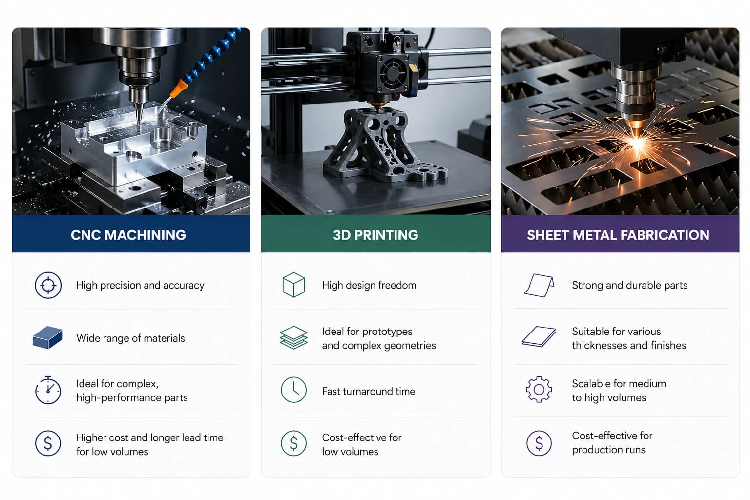
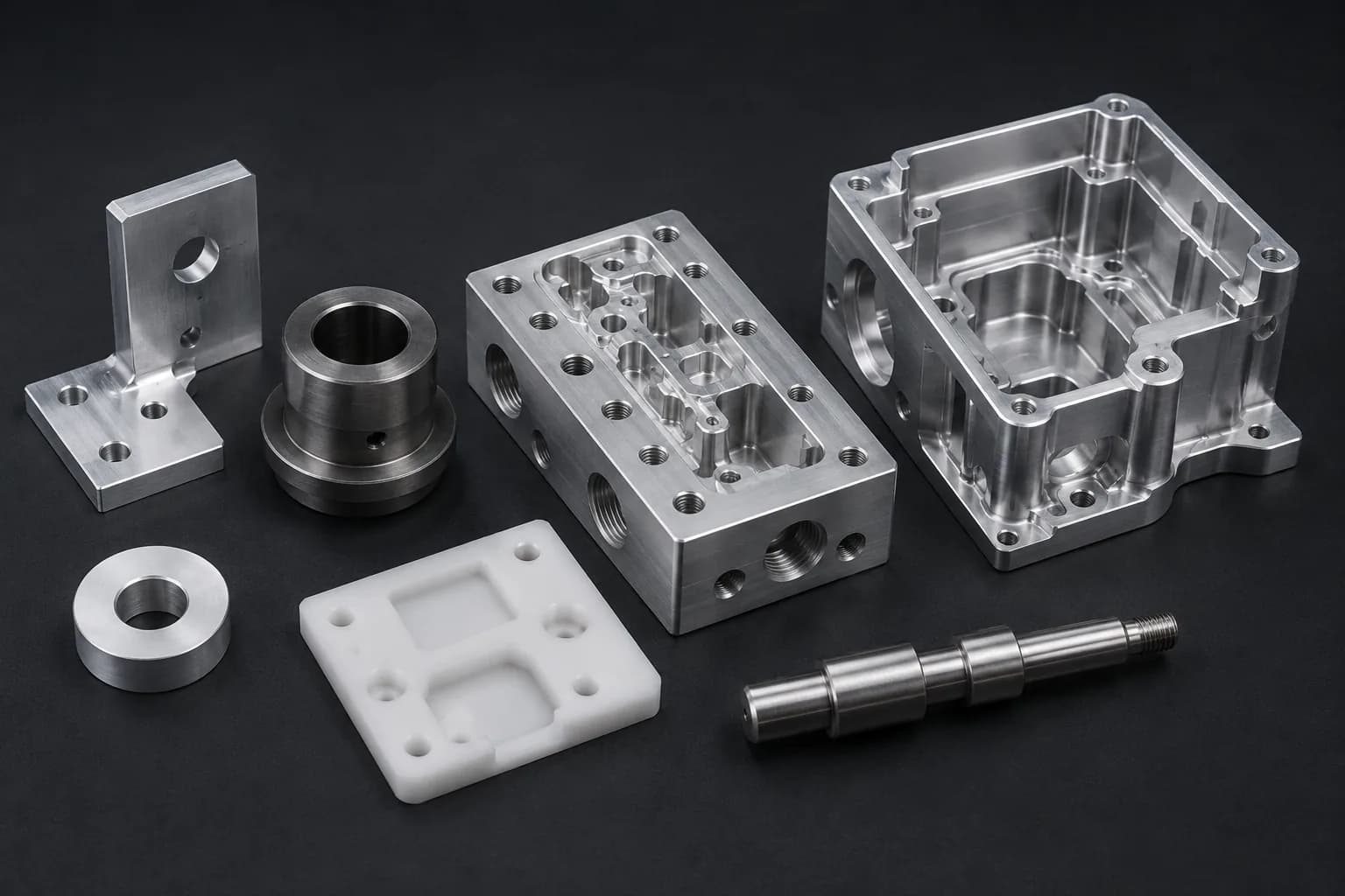
CNC Machining
CNC machining is ideal for producing high-precision parts with tight tolerances and strong mechanical properties. It works by removing material from a solid block, making it suitable for metals like aluminum and steel, as well as engineering plastics.
This process is commonly used for functional components, prototypes that require real material properties, and parts that need to be production-ready from the start.
3D Printing
3D printing services are best suited for rapid prototyping, complex geometries, and low-cost iteration. Unlike CNC machining, it is an additive process, meaning material is built layer by layer.
It is a strong option when speed is critical or when testing early-stage designs, but it may not always match the strength, surface finish, or precision of machined parts.
Sheet Metal Fabrication
Sheet metal fabrication is ideal for parts made from flat materials that are cut, bent, or formed into shape. This process is commonly used for enclosures, brackets, and structural components.
It is highly efficient for production and often more cost-effective than machining when the part design allows for it.
| Process | Best For | Limitations |
|---|---|---|
| CNC Machining | High-precision parts, tight tolerances, metals and engineering plastics | Material waste, higher cost for simple geometries |
| 3D Printing | Rapid prototyping, complex shapes, fast iteration | Lower strength, limited finishes, dimensional accuracy varies |
| Sheet Metal | Flat parts, enclosures, brackets, production runs | Limited to sheet-based geometries, requires design adaptation |
Selecting the right process early helps prevent redesigns, reduces cost, and ensures the final part meets performance expectations. In many cases, engineering teams will recommend the most efficient process based on your design and application.
If you're unsure which process to use, you can request a quote and receive guidance on the best manufacturing approach for your part.
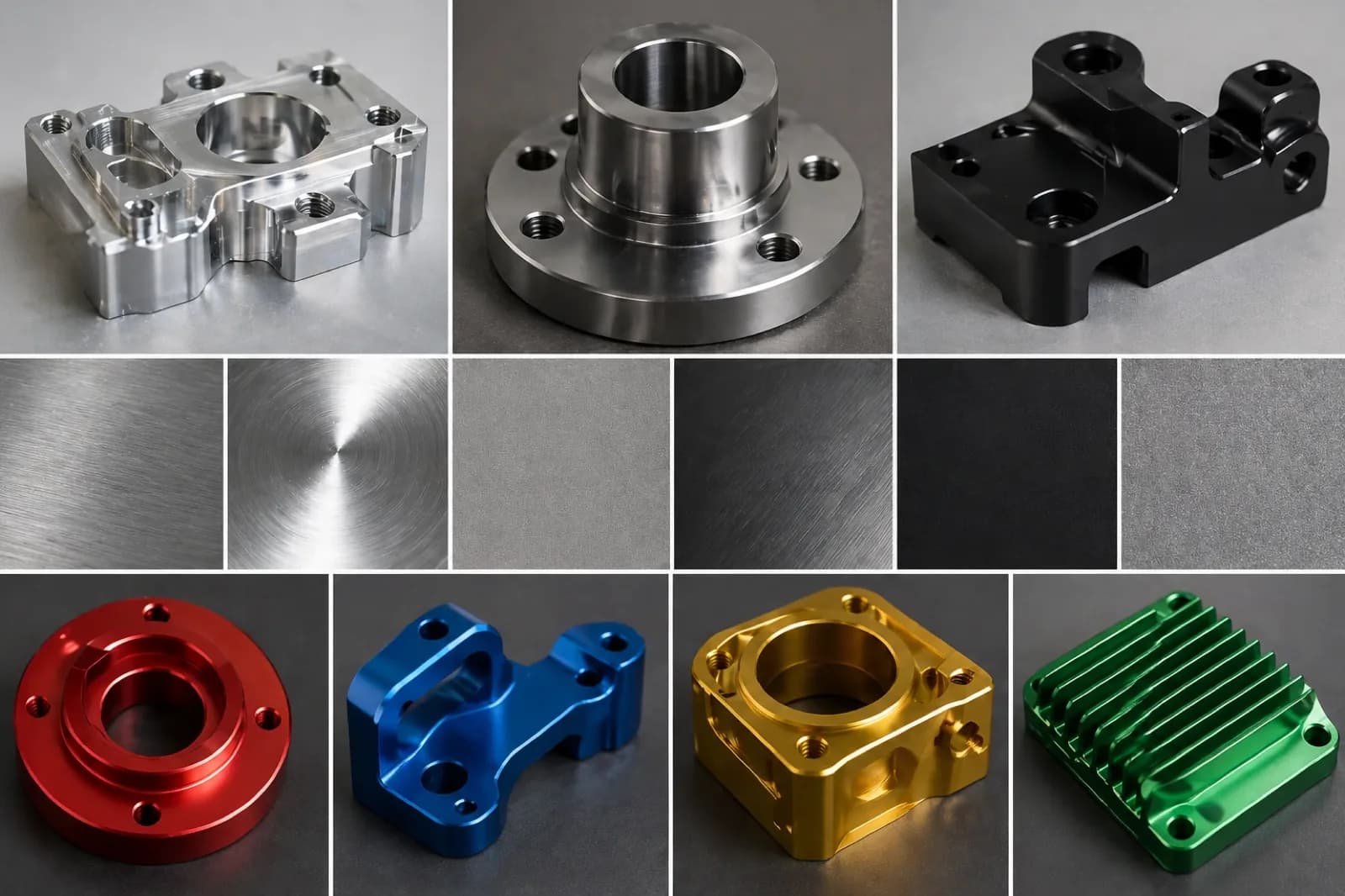
Step 3: Select Material & Surface Finish
After choosing the manufacturing process, the next step is selecting the right material and surface finish. This decision directly impacts strength, weight, durability, corrosion resistance, and overall cost.
Material selection should always be based on the function of the part, while surface finishes are typically used to enhance performance, protection, or appearance.
When working with CNC machining services, choosing the right combination early helps avoid redesigns, reduces machining complexity, and ensures consistent production results.
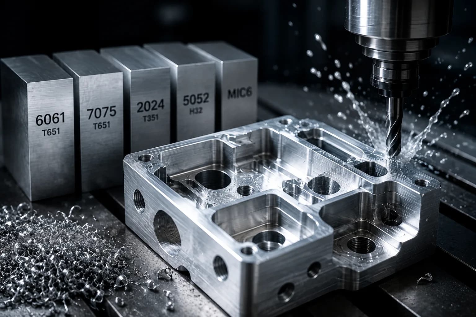
Common Materials for CNC Machining
CNC machining supports a wide range of metals and engineering plastics. The right choice depends on mechanical requirements, environment, and cost constraints.
- Aluminum 6061-T6 – Lightweight, corrosion-resistant, and highly machinable; ideal for prototypes and general-purpose parts
- Aluminum 7075-T6 – Higher strength than 6061; used in aerospace and high-performance applications
- Stainless Steel 304 – Excellent corrosion resistance and durability; widely used in industrial environments
- Stainless Steel 316 – Superior corrosion resistance, especially for marine or chemical applications
- Steel 1018 – Cost-effective low-carbon steel for general machining applications
- Steel 4140 – High-strength alloy steel suitable for mechanical and structural components
- Brass C360 – Easy to machine with excellent surface finish; ideal for fittings and precision components
- ABS – Common plastic for prototypes; lightweight and impact-resistant
- Nylon – Good wear resistance and flexibility; used for functional plastic components
- PEEK – High-performance plastic with excellent strength, temperature, and chemical resistance
- Amongst others
| Material | Best For | Key Considerations |
|---|---|---|
| Aluminum Alloys | Lightweight parts, prototypes, general applications | Excellent machinability, lower strength than steel |
| Steel & Alloy Steel | Structural parts, high-load applications | Higher strength, increased machining time and cost |
| Stainless Steel | Corrosion-resistant components | More difficult to machine, longer lead times |
| Brass & Copper Alloys | Precision parts, fittings, electrical components | Excellent finish, higher material cost |
| Engineering Plastics | Lightweight parts, insulation, chemical resistance | Lower strength, sensitive to temperature and load |
Common Surface Finishes for CNC Parts
Surface finishes are applied after machining to improve appearance, corrosion resistance, wear performance, or functionality. The right finish depends on the material and the intended use of the part.
- As Machined – Standard finish directly from the machine; fastest and most cost-effective
- Bead Blasting – Uniform matte texture for improved appearance
- Anodizing (Type II / Type III) – Corrosion resistance and color options for aluminum parts
- Powder Coating – Durable protective coating with a wide range of colors
- Black Oxide – Mild corrosion resistance for steel components
- Passivation – Enhances corrosion resistance for stainless steel
- Electropolishing – Improves surface finish and corrosion resistance in stainless parts
- Plating (Zinc / Nickel) – Adds corrosion protection and improves surface properties
- Amongst others
| Finish | Best For | Key Considerations |
|---|---|---|
| As Machined | Functional parts with no cosmetic requirements | Visible tool marks, no added protection |
| Anodizing | Aluminum parts requiring corrosion resistance and aesthetics | Adds cost and processing time |
| Powder Coating | Durable protective finish with color | Thicker coating, may affect tolerances |
| Black Oxide | Steel parts requiring light corrosion protection | Limited durability compared to coatings |
| Passivation | Stainless steel corrosion resistance | Does not change appearance significantly |
| Plating | Enhanced corrosion resistance and surface properties | Additional process step increases lead time |
Selecting the right material and finish combination ensures your part performs as expected without unnecessary cost. In many cases, engineering teams can suggest alternatives that provide the same functionality with improved manufacturability.
If you're unsure which material or finish is best, you can request a quote and receive recommendations based on your design and application.
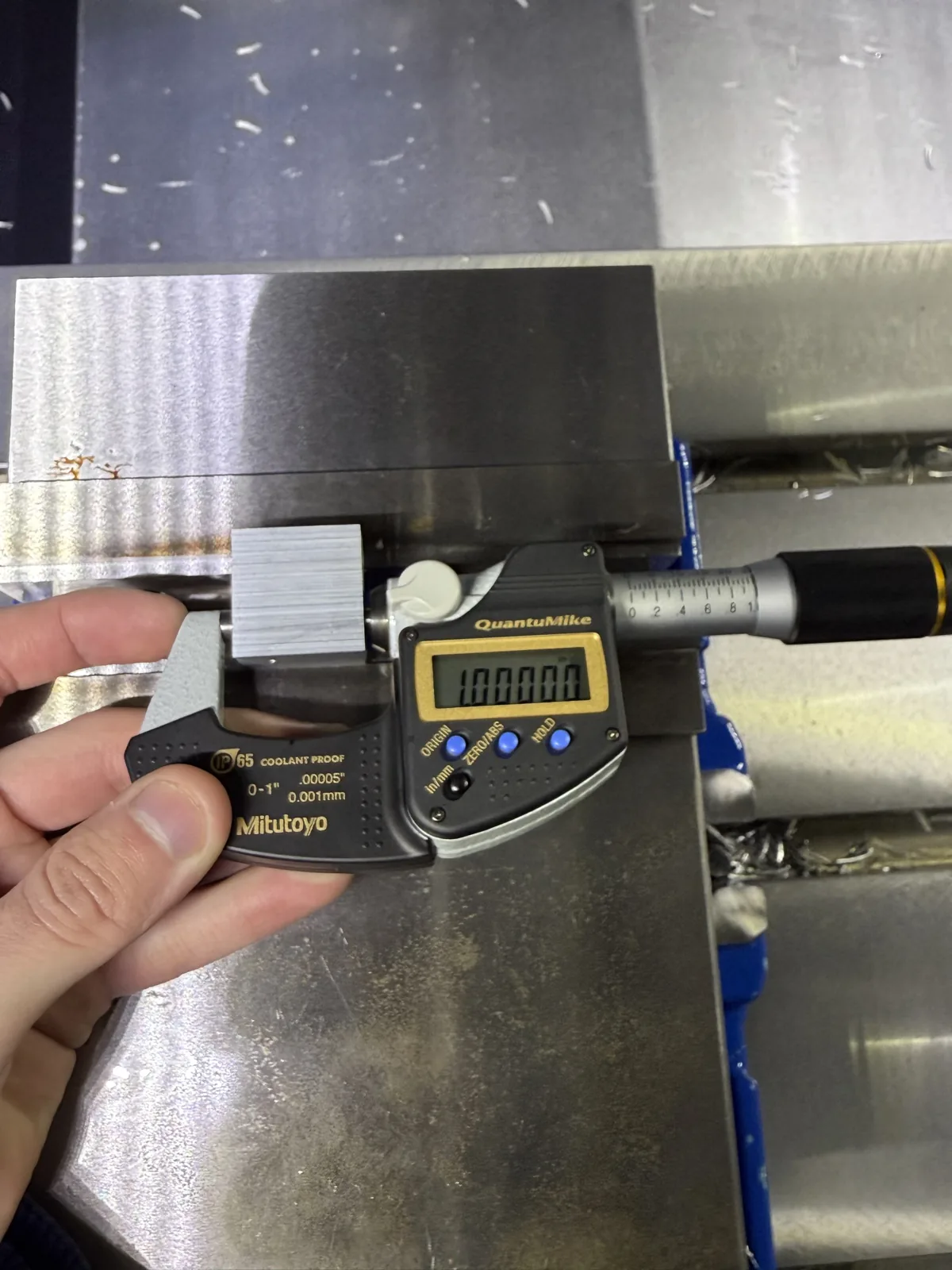
Step 4: Define Tolerances & Specifications
Once your material and process are defined, the next step is specifying tolerances and critical requirements. Tolerances define the allowable variation in a part’s dimensions and are one of the main factors that influence machining complexity, inspection requirements, and overall cost.
In CNC machining, tighter tolerances require more precise setups, slower machining speeds, and additional quality control, which increases both cost and lead time. For this reason, tolerances should only be applied where they are functionally necessary.
In most cases, CNC machined parts follow general tolerance standards such as ISO 2768 medium, which define acceptable dimensional variation when specific tolerances are not explicitly indicated. These standards help streamline production and avoid unnecessary over-specification.
ISO 2768 General Tolerances
ISO 2768 defines general tolerances for linear and angular dimensions when no specific tolerance is provided on the drawing. The most commonly used classes for CNC machining are 'm' (medium) and 'f' (fine), depending on the required level of precision.
| Dimension Range | ISO 2768-m (Medium) | ISO 2768-f (Fine) |
|---|---|---|
| 0.5 – 3 mm | ±0.1 mm | ±0.05 mm |
| 3 – 6 mm | ±0.1 mm | ±0.05 mm |
| 6 – 30 mm | ±0.2 mm | ±0.1 mm |
| 30 – 120 mm | ±0.3 mm | ±0.15 mm |
| 120 – 400 mm | ±0.5 mm | ±0.2 mm |
When to Apply Tighter Tolerances
While ISO general tolerances are sufficient for most parts, tighter tolerances should be specified for features that directly affect assembly, fit, or performance. These include mating surfaces, bearing fits, threaded features, and sealing interfaces.
Over-specifying tight tolerances across an entire part is one of the most common mistakes in CNC machining. It increases machining time and inspection requirements without improving functionality.
- Apply tight tolerances only to critical functional features
- Use general tolerances (ISO 2768 medium) for non-critical dimensions
- Avoid unnecessary ±0.01 mm tolerances unless required
- Consider fit requirements for assemblies (clearance, interference, transition)
Additional Specifications to Include
Beyond dimensional tolerances, clearly defining part specifications helps ensure accurate quoting and consistent production results.
- Thread specifications (size, pitch, depth, standard)
- Surface finish requirements (Ra values or coatings)
- Geometric tolerances if required (flatness, perpendicularity, concentricity)
- Material grade and heat treatment (if applicable)
- Special requirements such as deburring, marking, or inspection reports
Defining tolerances and specifications correctly allows engineering teams to optimize the machining process, reduce cost, and ensure the part performs as intended. In many cases, reviewing tolerances early can lead to significant savings without compromising quality.
If you're unsure how to apply tolerances to your design, you can request a quote and receive guidance on the appropriate specifications for your application.
Step 5: Prepare Your Files for Quoting
Before submitting a quote request, it is important to ensure your files are complete, clear, and ready for evaluation. Well-prepared files reduce back-and-forth communication, speed up the quoting process, and help avoid delays once production begins.
In CNC machining, incomplete or unclear information is one of the main causes of misquotes, manufacturing issues, and extended lead times.
Most CNC machining services accept standard 3D file formats, along with optional documentation that helps define critical requirements.
Accepted File Formats
Providing the correct file format ensures that engineers can review your design accurately and generate a reliable quote.
- STEP (.step / .stp) – Preferred format for CNC machining due to precise geometry
- STL (.stl) – Common for prototypes, but may lack dimensional detail
- DXF (.dxf) – Used for 2D profiles, especially in sheet metal parts
- PDF Drawings – Useful for dimensions, tolerances, and special instructions
What Information to Include
Beyond the file itself, including complete project details helps ensure accurate pricing and avoids unnecessary revisions.
- Material selection and grade
- Surface finish requirements
- Tolerances and critical dimensions
- Quantity (prototype vs production)
- Threads, inserts, or special features
- Any additional notes or functional requirements
Common Mistakes to Avoid
Many delays in quoting and production come from missing or unclear information. Avoiding these common mistakes helps streamline the entire process.
- Uploading incomplete or outdated files
- Not specifying material or finish
- Overlooking tolerance requirements
- Missing dimensions or unclear drawings
- Not indicating quantity or intended use
Taking the time to prepare your files properly allows engineering teams to review your project faster, provide accurate pricing, and identify potential improvements before production.
If your files are ready, you can request a quote and receive feedback on manufacturability, cost, and lead time—often within a short turnaround.
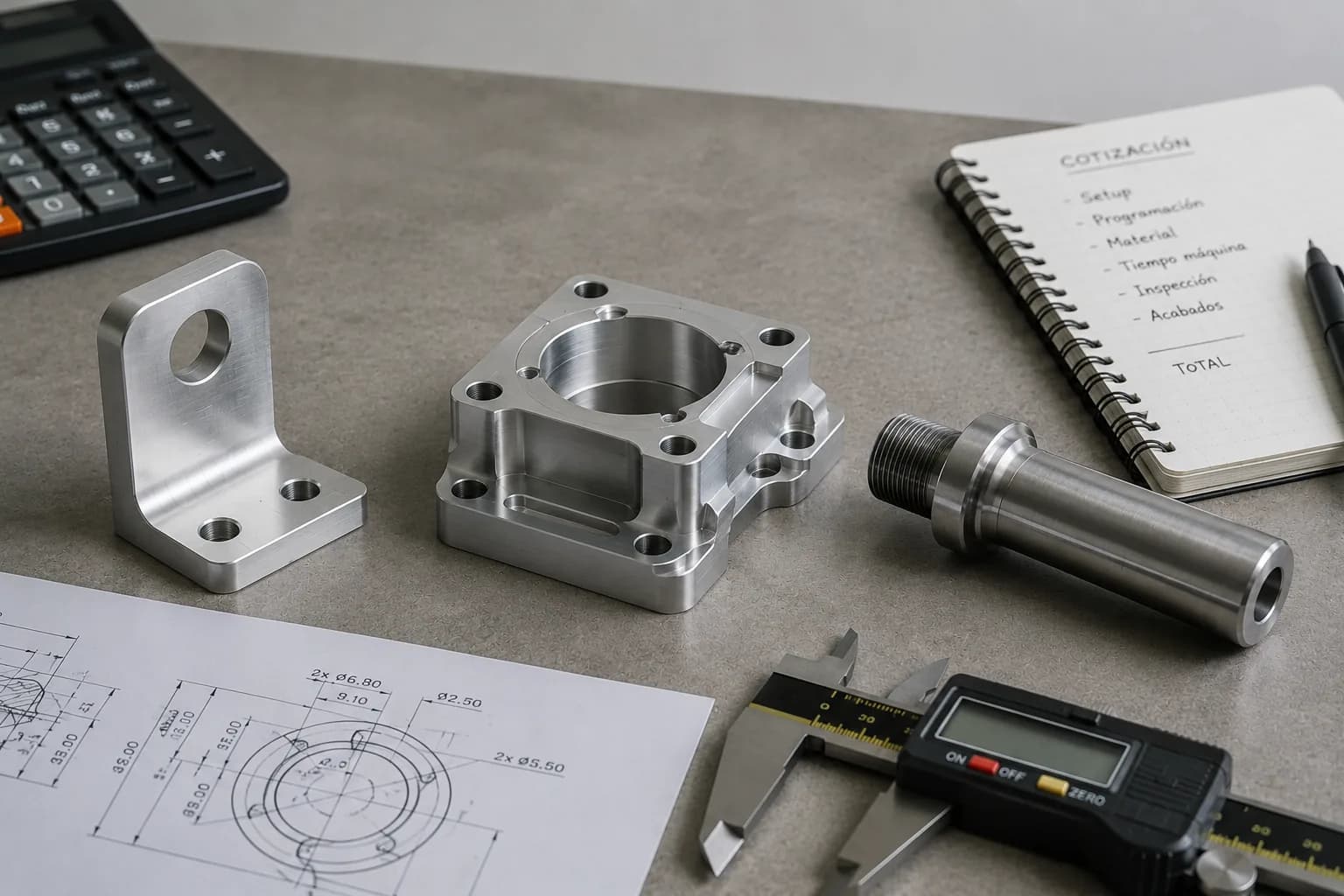
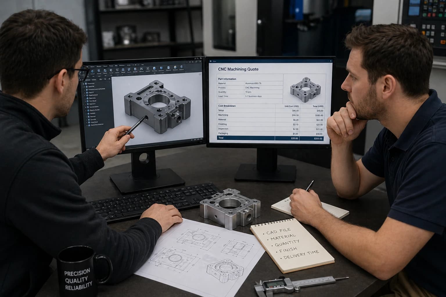
Step 6: Submit a Quote & What Happens Next
Once your files and specifications are ready, the next step is submitting a quote request. At this stage, the goal is not just to receive a price, but to validate manufacturability, optimize cost, and define a realistic lead time.
Submitting a quote allows engineering teams to review your design in detail and ensure it can be produced efficiently without issues during production.
When you work with CNC machining services, the quoting process is typically followed by a structured engineering review and production workflow. Understanding what happens next helps eliminate uncertainty and ensures a smoother experience.
Pricing is determined based on material, part complexity, tolerances, and quantity. For a detailed explanation of how pricing works, refer to CNC machining cost breakdown.
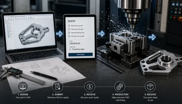
What Happens After You Submit a Quote
After submitting your files, your project typically goes through several key steps before production begins.
- RFQ Received – Your files and requirements are reviewed for completeness
- Engineering Review (DFM) – Manufacturability is evaluated and potential improvements are identified
- Quote Preparation – Pricing and lead time are calculated based on material, complexity, and quantity
- Customer Approval – You review the quote and confirm the order
- Production & Quality Control – Parts are manufactured and inspected before delivery
Engineering Review & Optimization
One of the most valuable parts of the quoting process is the engineering review. This step ensures that your design is not only manufacturable, but also optimized for cost and efficiency.
In many cases, small adjustments—such as modifying tolerances, simplifying features, or selecting alternative materials—can significantly reduce machining time and overall cost without affecting performance.
Lead Time & Production Planning
Lead time depends on several factors, including part complexity, material availability, required finishes, and production volume. Prototypes are typically delivered faster, while production runs may require additional planning and coordination.
Clear communication during the quoting phase helps set accurate expectations and ensures the project moves forward without delays.
Submitting a quote is not just a pricing step—it is the starting point of a structured manufacturing process designed to ensure quality, efficiency, and reliability.
If your design is ready, you can request a quote and move your project from concept to production with engineering support at every step.
Common Mistakes When Ordering CNC Parts
Even with a complete design, many issues in CNC machining come from small mistakes during the ordering process. Avoiding these common problems can save time, reduce cost, and prevent delays.
- Applying unnecessarily tight tolerances across the entire part
- Selecting materials without considering performance requirements
- Designing features that are difficult or expensive to machine
- Submitting incomplete or unclear files
- Not specifying finishes or critical requirements
- Ignoring manufacturability feedback during the quoting stage
Most of these issues can be resolved early through proper design and engineering review. Addressing them before production helps ensure smoother manufacturing and better overall results.
Ready to Get Your CNC Parts Made?
Getting CNC parts manufactured does not have to be complicated. By following the right steps—from design and material selection to tolerances and file preparation—you can move from concept to production with confidence.
Working with experienced engineering teams ensures your design is optimized for manufacturability, cost, and performance from the start.
If your design is ready, you can request a quote and receive expert feedback along with accurate pricing and lead time for your project.
If you are preparing or optimizing designs, see our CNC machining design guide.

Written by
Adrian Cavazos and the PREMSA Engineering Team
Adrian Cavazos, founder of PREMSA Industries, leads a manufacturing engineering team specialized in CNC machining, metal fabrication, and production-ready solutions. The team works closely with customers to optimize designs, improve manufacturability (DFM), and ensure reliable, scalable production from prototypes to volume manufacturing.