PrecisionSheet Cutting
Engineering-driven 2D cutting for brackets, panels, plates, templates, and flat components. Clean edges, repeatable accuracy, and material-efficient nesting—built for prototypes and scalable production.
Cut Tolerance
±0.005" (typ.)
Fast-Track
2–5 Days
Thickness Range
0.020"–0.500"
In-house process
Cutting, deburring, and inspection under one roof.
Sheet Cutting Services
Engineering-First Sheet Cutting for Accurate 2D Parts
PREMSA delivers sheet cutting built around repeatability and edge quality—controlled kerf, consistent feature placement, and clean profiles that match your drawing intent. We review your DXF/flat patterns early to prevent scrap from missing reliefs, feature collisions, or overly tight tolerances.
Our process is optimized for real cutting constraints: minimum feature size, edge distance rules, corner quality, heat input, and distortion risk. We focus on getting you accurate flat parts fast—while keeping cost and lead time predictable.
From rapid prototypes to production runs, PREMSA supports optional deburr/edge prep and part identification. We align inspection to the features that drive fit: hole-to-hole, hole-to-edge, mating patterns, and interface geometry.
What is Sheet Cutting?
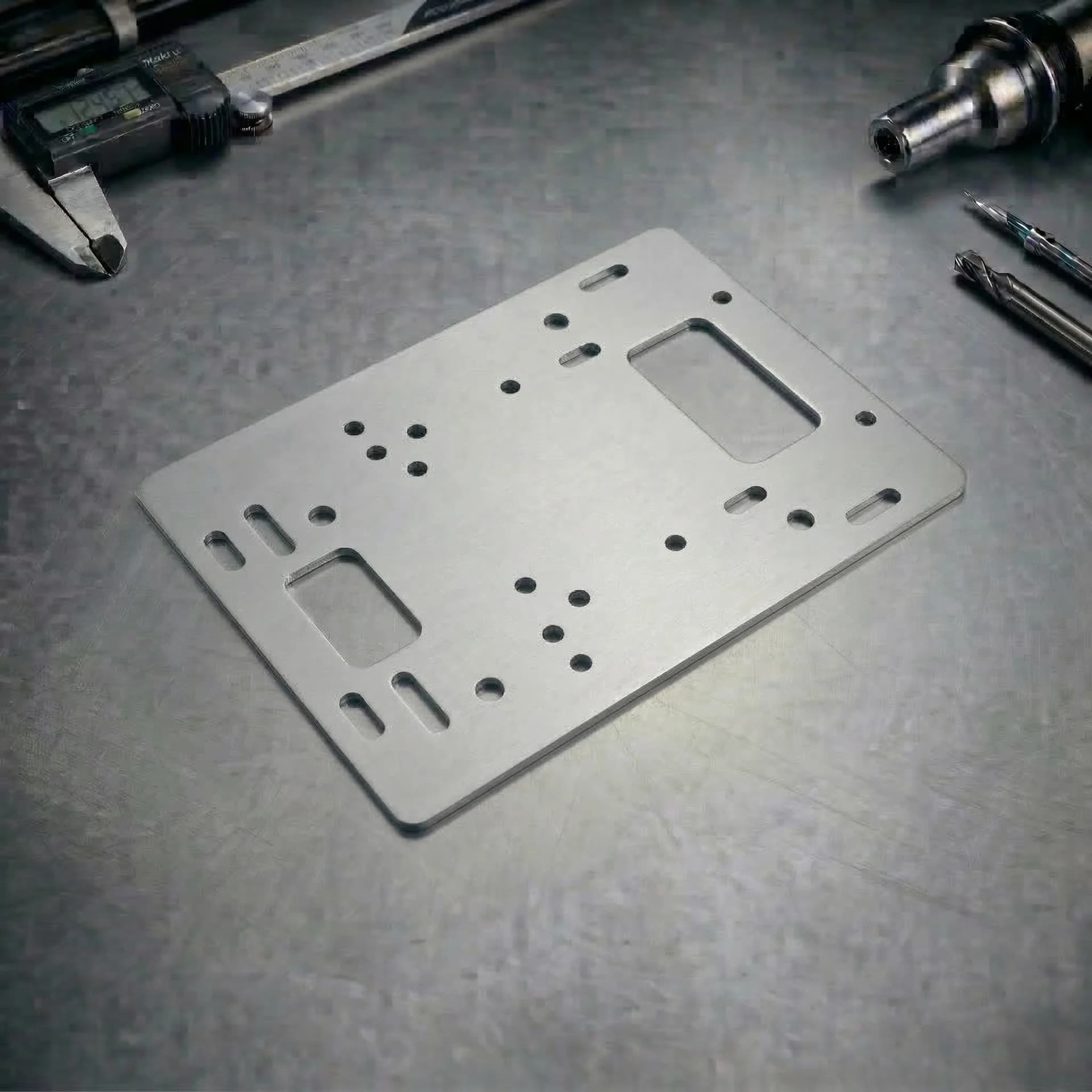
Sheet cutting is a 2D manufacturing process that creates flat parts from sheet or plate by cutting profiles, holes, slots, and contours using laser cutting, waterjet cutting, or CNC routing depending on material, thickness, and edge quality requirements.
It is ideal for flat brackets, panels, base plates, templates, guards, shims, and mounting plates where fast turnaround, repeatable hole patterns, and clean edges matter.
The Cutting Workflow
An engineering-driven process designed to control edge quality, accuracy, and repeatability for sheet cutting parts.
1. File Intake & Scope Definition
We receive 2D drawings and DXF files and confirm part scope, quantities, materials, thickness, and delivery requirements before production planning begins.
2. Drawing & DXF Validation
Units, scale, revision control, feature intent, edge distances, and CTQ dimensions are validated to prevent errors or scrap before cutting.
3. Manufacturability Review (DFM)
Features are reviewed against process limits including minimum feature size, internal corner quality, spacing rules, and distortion risk.
4. Process Selection
The cutting method—laser, waterjet, or CNC routing—is selected based on material behavior, thickness, tolerance requirements, and edge quality expectations.
5. Cut Strategy Definition
We define kerf or tool diameter compensation, lead-ins and lead-outs, cut order, retention strategy, and quality targets for functional or cosmetic edges.
6. Cutting & Monitoring
Parts are cut using controlled parameters to maintain consistency across the batch. Heat input, taper, vibration, or chatter are actively managed depending on the selected process.
7. Edge Preparation & Secondary Ops
Deburring, edge break, or surface preparation is applied when specified to improve handling safety, fit, and readiness for downstream operations.
8. Inspection & Final Release
Critical features are inspected using calibrated tools. Parts are released only after CTQ dimensions and overall quality requirements are met.
Core Cutting Capabilities
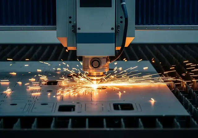
Laser Cutting (Sheet / Plate)
High-precision 2D cutting for complex outlines, patterns, and internal features. Best for fast-turn parts requiring clean edges, tight feature placement, and repeatable accuracy on thin to medium thickness materials.
WaterJet Cutting (Sheet / Plate)
Cold-cut profile cutting for thicker plate or heat-sensitive materials. Eliminates heat-affected zones and supports demanding geometries where laser heat input or distortion is a concern.
CNC Routing (Non-Metals)
High-speed 2D cutting for plastics and non-metal sheets such as acrylic, Delrin, and boards. Ideal for panels, templates, covers, and insulated components where laser is not preferred.
2D Profile Cutting (DXF-Driven)
Contours, holes, slots, and cutouts produced from DXF/flat geometry. Process selection (laser, waterjet, or routing) is matched to material, thickness, edge quality requirements, and cost.
Thin Sheet Control
Process-specific strategies to manage distortion, chatter, or taper depending on cutting method—laser sequencing, waterjet parameters, or routing hold-down techniques.
Deburr & Edge Prep
Post-cut edge preparation to remove sharp edges, improve handling safety, and support assembly or finishing readiness without altering functional geometry.
Technical Advantages
Fast Turnaround for Flat Parts
Efficient DXF-to-cut workflow optimized for speed—ideal for prototypes, spares, and production kits.
Repeatable Hole Patterns & Profiles
Kerf compensation and controlled cutting strategies improve consistency across production runs.
Material-Efficient Nesting
Nesting optimization reduces scrap and stabilizes cost across quantity—especially on large sheet formats.
Cleaner Edges for Assembly
Edge prep options improve handling safety and help parts seat correctly against mating surfaces.
Process Matched to CTQ
We focus effort where it matters: patterns, interfaces, and functional edges—avoiding unnecessary cost drivers.
Inspection Aligned to Fit
Verification targets hole-to-hole, hole-to-edge, and interface geometry that drives real-world assembly performance.
Cutting Capacity & Envelope
Sheet Size
Typical production sheet formats supported for cutting and nesting. Oversize formats may be reviewed case-by-case.
Up to 48" × 96" (typ.)
Thickness Range
Supported thickness depends on material type and edge quality requirements (thin sheet heat control vs plate cutting).
0.020" – 0.500"
Detail Capability
Feature capability depends on thickness, kerf, and edge distance rules. Small holes and tight corners may require review or alternate strategy.
Small features reviewed case-by-case
Complex Profiles or Tight Features?
If your parts include micro-holes, tight internal corners, dense perforation patterns, or thin-sheet warp risk, request a cut strategy assessment before release.
Tolerances & GD&T
Cut accuracy depends on material, thickness, part size, and cut strategy (kerf, pierce, sequencing, and heat input). Defining critical-to-quality (CTQ) dimensions helps control cost while protecting fit and function.
| Category | Technical Capability | Engineering Notes |
|---|---|---|
| Cut Tolerances | Cut tolerances depend on the selected process (laser, waterjet, or CNC routing), material type, thickness, part size, and feature density. Tight tolerances may require conservative parameters or secondary operations. | Apply tight tolerances only to CTQ features. Blanket tight tolerances increase cost without improving function. |
| Feature Limits & Edge Quality Drivers | Minimum feature size, internal corner quality, kerf or tool diameter, and edge taper vary by process. Laser, waterjet, and routing each impose different limits on holes, slots, and sharp internal corners. | Avoid features smaller than material thickness. Internal radii improve edge quality and process stability across all cutting methods. |
| Flatness & Process Effects | Laser cutting may introduce heat distortion on thin sheet, waterjet can introduce taper on thick plate, and routing may cause vibration or chatter if not properly supported. | Process selection and sequencing are adjusted to protect flatness and edge quality for large or thin parts. |
| Inspection & Verification | Inspection focuses on CTQ dimensions such as hole-to-hole, hole-to-edge, pattern location, and interface geometry using calibrated measurement tools. | Provide datums and inspection notes for functional features to ensure fit and repeatability. |
Sheet & Plate Materials
Choose from production-grade metals and cuttable non-metals. Material selection impacts bendability, edge quality, corrosion resistance, electrical performance, and cosmetic finish.
Metals (Sheet / Plate)
Non Metal Materials
Surface Finishes
Surface finishing improves corrosion resistance, wear life, and cosmetic appearance. Finishes should be selected based on environment, assembly requirements, and long-term durability.
Finish Options
Sheet Cutting DFM Guidelines (DFM)
Cut part manufacturability is driven by feature sizing, edge distance rules, internal corners, and heat input. Following these DFM rules reduces scrap, improves edge quality, and increases repeatability in production.
| Design Feature | Recommendation |
|---|---|
| Corner Radii, Reliefs & Process Effects | Avoid extremely sharp internal corners. Add internal radii or reliefs to improve edge quality and process stability. Heat input (laser), taper (waterjet), or tool radius (routing) must be considered. |
| Holes, Slots & Edge Distance | Keep holes and slots away from edges to prevent breakout, distortion, or weak ligaments. Very small features relative to thickness may require alternate process selection. |
| Feature-to-Feature Spacing Rules | Maintain adequate spacing between features to protect edge quality and avoid overlapping heat zones, taper interaction, or tool interference. |
| Tabs, Notches & Part Identification | Tabs, notches, or reference marks may be used for part retention, identification, or downstream handling depending on process and material. |
| Threads, Countersinks & Secondary Operations | Cut features are not a substitute for precision threads or countersinks. Specify when secondary drilling, tapping, or machining is required for functional interfaces. |
| Drawing & DXF Checklist | Provide a 2D drawing with material, thickness, finish, and CTQ dimensions. Include correct units, scale, datums, and revision control. DXF must represent final cut geometry. |
Applications & Industries
Sheet Cutting Applications
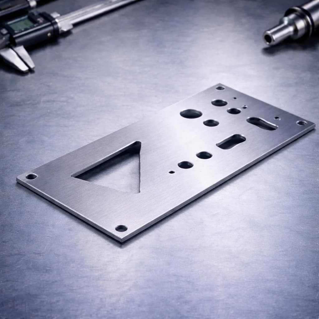
Mounting Plates & Base Plates
Flat plates with repeatable hole patterns for fixtures, equipment mounting, and industrial frames.
Panels, Covers & Guards
Cut-to-shape panels and protective guards with clean edges and optional deburr for safe handling.
Brackets, Tabs & Flat Hardware
2D brackets and flat hardware for assemblies requiring fast turnaround and consistent geometry.
Sheet Cutting Industries
Manufacturing
Laser-cut plates, brackets, gussets, and machine components used in equipment builds and production tooling.

Energy
Precision-cut steel and aluminum plates for structural supports, electrical enclosures, and energy infrastructure components.

Electronics and Semiconductors
Flat precision-cut panels, mounting plates, and shielding components used in electronic systems and semiconductor equipment.

FAQs & Knowledge Base
Sheet Cutting FAQs
Sheet cutting services
Sheet cutting is often the first operation in a fabricated part: nested blanks optimized for material use, tight contour accuracy, and repeatable hole patterns. PREMSA feeds cutting output directly into bending, fabrication, and assembly workflows.
Link to sheet metal fabrication and sheet metal bending for downstream operations.
PREMSA ecosystem
Services, guides, and tools for sheet cutting
We operate from Monterrey for engineering teams across Mexico and North America. We deliver laser and plasma cutting for flat blanks and kits with ISO 2768 tolerances, engineering materials, and prototype-to-production routes. Use the technical references below and quote online with STEP or STL files.
Metal fabrication processes
Engineering tools
- Interactive chart
ISO 2768 Tolerance Chart
Look up general linear and geometric tolerances for sheet metal and machined features.
View chart - Calculator
Tap Drill Size Calculator
Calculate tap drill sizes for PEM inserts, threaded holes, and formed features.
Open tool - Reference chart
Drill Bit Size Chart
Reference drill diameters for clearance holes and hardware prep in fabricated assemblies.
View chart
- What files should I upload for sheet cutting parts?
- Best practice is a 2D drawing (PDF) for requirements plus a DXF for cut geometry. Include correct units/scale, revision control, and CTQ callouts (hole-to-hole, hole-to-edge, interfaces).
- Can you cut holes, slots, and complex profiles?
- Yes. We cut complex outlines, holes, and slots from DXF/2D geometry. Small features and tight internal corners may require DFM review to protect edge quality and repeatability.
- Do you provide deburring or edge break?
- Yes. Deburr and edge break are common post-process steps to remove sharp edges, improve handling safety, and support assembly fit.
- How do tolerances work for sheet cutting?
- Cut tolerances depend on material, thickness, part size, and feature density. We recommend tight tolerances only on CTQ dimensions such as hole patterns, interfaces, and functional edges. Reference our ISO 2768 chart, tap drill calculator, and drill bit size chart when specifying holes and threads.
- Can you provide finishing after cutting?
- Yes, when specified. Common options include surface prep, powder coating, plating, anodizing (aluminum), and passivation (stainless). Finish selection should match corrosion and cosmetic needs.
- What drives cost the most in sheet cutting?
- Primary drivers are material grade/thickness, overall cut length, feature density, small features, tight CTQ tolerances, deburr/edge prep requirements, and yield (nesting efficiency).
Ready for your next project with PREMSA?
Upload your STEP file, set material and quantity, and get DFM review with clear lead times and an online quote.