
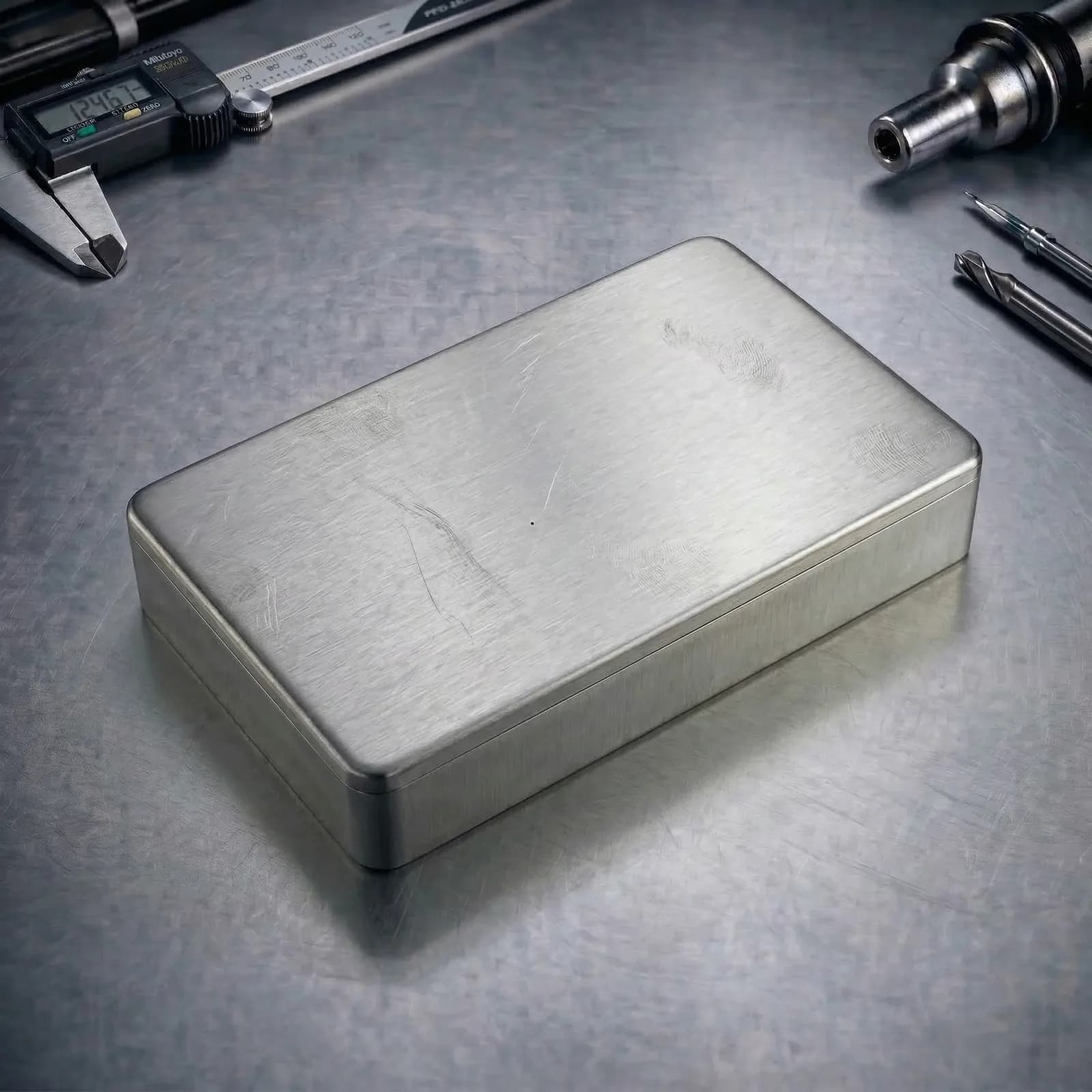
PrecisionSheet Metal Fabrication
Engineering-driven fabrication for brackets, panels, enclosures, and welded assemblies. From clean laser edges to repeatable bends and hardware insertion—built for prototypes and scalable production.

Cut Tolerance
±0.005" (typ.)
Fast-Track
3–7 Days
Thickness Range
0.030"–0.500"
In-house process
Cutting, forming, deburring, and inspection under one roof.
Sheet Metal Fabrication Services
Engineering-First Fabrication for Production Assemblies
PREMSA delivers sheet metal fabrication built around manufacturability and repeatability—clean cut edges, controlled bend geometry, and consistent part-to-part fit. We review your drawings and flat patterns early to reduce rework, improve assembly alignment, and prevent tolerance stack issues.
Our process is optimized for real-world fabrication constraints: bend radii, reliefs, hardware clearance, and weld access. We focus on what makes a part function and assemble correctly—while keeping cost and lead time predictable.
From rapid prototypes to scalable production, PREMSA supports finishing, hardware insertion, and assembly-ready documentation. We deliver parts that match your intent with inspection plans aligned to the critical dimensions that actually drive fit and performance.
What is Sheet Metal Fabrication?
Sheet metal fabrication is a manufacturing process that transforms flat sheet or plate into functional components using cutting (laser/punch), forming (bending), and secondary operations such as hardware insertion, welding, and finishing.
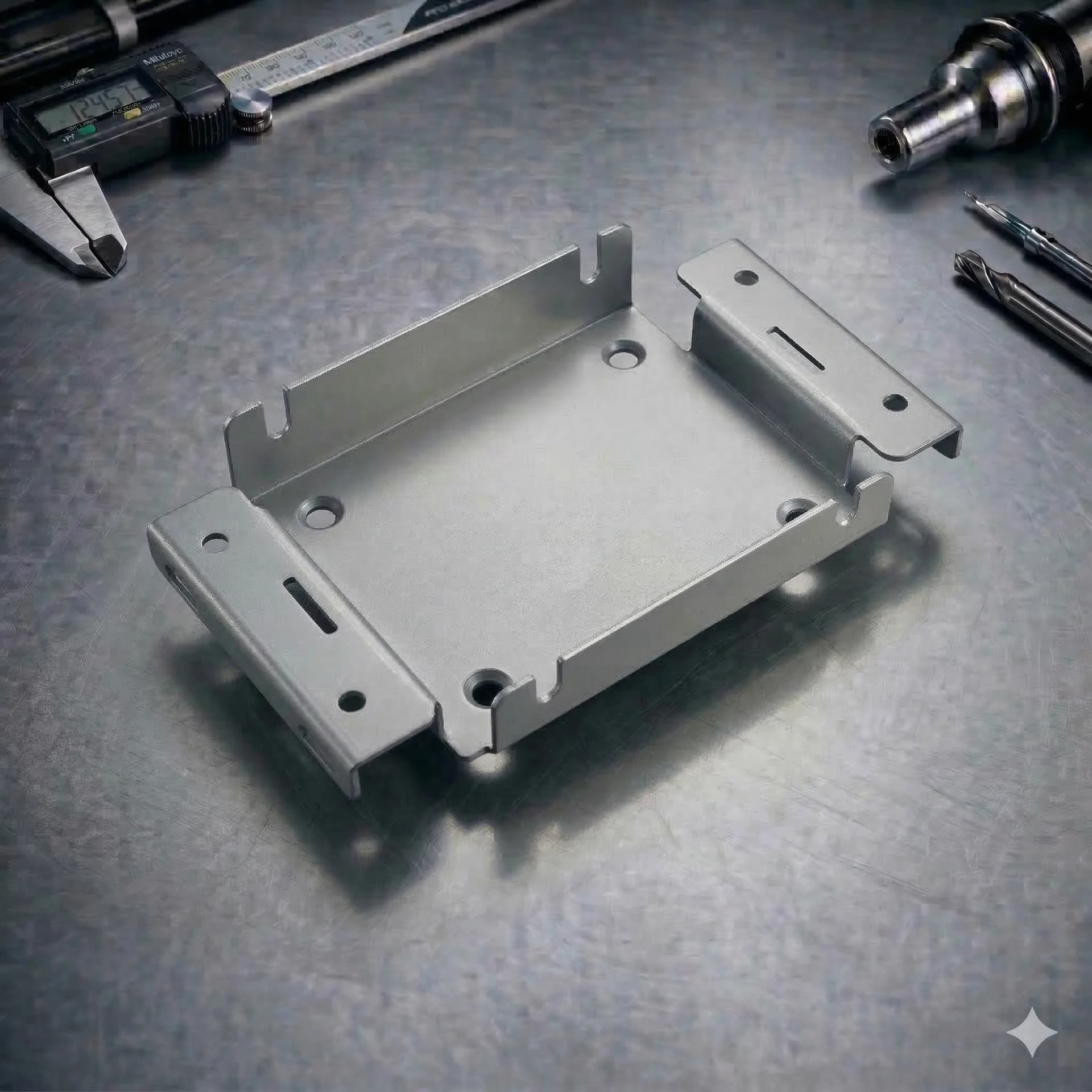
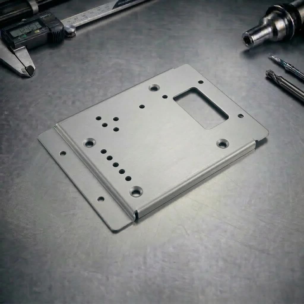
It is ideal for brackets, panels, enclosures, chassis, guards, and structural sub-assemblies where lightweight strength, efficient material usage, and repeatable geometry matter.
The Fabrication Workflow
A controlled engineering process optimized for fit, cosmetic quality, and production repeatability.
1. DFM + Print Review
We review drawings and models to validate bend intent, hole-to-bend rules, hardware clearance, weld access, and inspection targets. Risks such as distortion, over-tolerancing, and missing reliefs are flagged early.
2. Material & Process Selection
Material, thickness, and fabrication methods are confirmed based on functional requirements, cosmetic needs, and production volume. Grain direction and finishing constraints are considered where applicable.
3. Flat Pattern Validation & Nesting
Flat pattern logic is verified using the appropriate bend allowance or K-factor strategy. Nesting is optimized for material yield, part stability, and downstream forming efficiency.
4. Cutting (Laser / Punch)
Profiles, holes, slots, and tabs are cut with controlled kerf and edge quality. Parts are identified and organized to maintain traceability through forming and assembly.
5. Forming (Press Brake)
Bends are formed using the correct tooling to control inside radius, angles, and flange lengths. Bend sequencing is planned to avoid collisions and feature distortion.
6. Secondary Operations
Deburring, edge breaking, hardware insertion (PEM), tapping, welding, and other secondary processes are completed according to specification.
7. Finishing & Surface Protection
Surface finishes such as powder coating, plating, anodizing, or passivation are applied as required, with masking and handling practices aligned to cosmetic expectations.
8. Inspection & Release
Critical-to-quality (CTQ) dimensions are verified using calibrated tools and fixtures. Inspection effort is focused on features that directly impact fit, function, and assembly.
Procesos Clave de Fabricación
Corte Láser
Corte de perfiles de alta precisión para metales y algunos no metálicos. Ideal para geometrías complejas, nesting eficiente y bordes limpios en brackets y paneles.
Punzonado (Cuando Aplica)
Creación rápida de orificios y características repetitivas. Eficiente para altos volúmenes con geometría compatible con herramental estándar.
Doblado en Prensa
Dobleces controlados para gabinetes, pestañas, canales y formas estructurales. La selección de herramental define radio, control angular y calidad cosmética.
Inserción de Herrajes (PEM)
Separadores, tuercas, espárragos y herrajes cautivos para ensambles listos, reduciendo tornillería suelta y mejorando el servicio.
Soldadura y Ensamble
Subensambles soldados con planeación de acceso y control de deformación. Incluye estrategia de punteo, secuencia y acabado post-soldadura.
Acabados y Post-Procesos
Procesos como desbarbado, rompimiento de aristas, pintura en polvo, recubrimientos y pasivado para cumplir requisitos de corrosión, estética y ensamble final.
Technical Advantages
Fast Prototyping to Production
Efficient workflows from DXF/STEP to cut, form, and finish—ideal for design iterations and scalable builds.
Repeatable Bends & Fit
Controlled forming and DFM-based flat patterns reduce assembly issues and improve part interchangeability.
Efficient Material Utilization
Nesting and standard gauge selection reduce scrap and stabilize cost across volume.
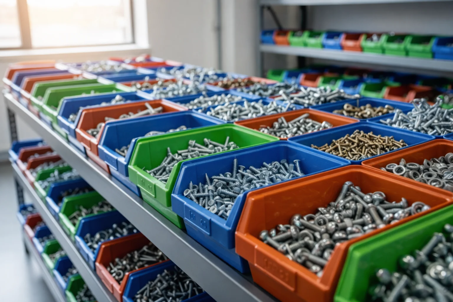
Assembly-Ready Hardware
PEM insertion and tapping integrate fastening features directly into the part to streamline assembly.
Finishing for Function & Aesthetics
Powder coat, plating, anodize, and passivation options to meet corrosion, wear, and cosmetic targets.
Inspection Aligned to CTQ
We focus inspection on what drives function: hole-to-hole, hole-to-bend, critical flange lengths, and mating interfaces.
Fabrication Capacity & Envelope
Sheet Size
Typical production sheet formats supported for cutting and nesting. Oversize formats may be reviewed case-by-case.
Up to 48" × 96" (typ.)
Thickness Range
Supported thickness depends on material type and process (cutting and forming constraints).
0.030" – 0.500"
Forming Capacity
Press brake forming for common flanges, channels, and enclosure geometry. Long bends and heavy gauges may require review.
Up to 8 ft bends (typ.)
Custom Requirements?
For heavy plate, oversized sheets, complex multi-bend enclosures, or tight cosmetic requirements, request a specialist engineering assessment.
Tolerances & GD&T
Sheet metal accuracy depends on process selection (laser vs punch), thickness, material condition, and bend geometry. Defining critical-to-quality (CTQ) dimensions helps control cost while protecting fit and function.
| Category | Technical Capability | Engineering Notes |
|---|---|---|
| Cut Tolerances | Typical profile and hole position tolerances are influenced by thickness and part size. Tight tolerances may require slower cutting strategy or secondary machining. | Use tighter callouts only on CTQ features; avoid blanket tight tolerances on all edges. |
| Bend Control | Angle and flange length depend on tooling, bend radius, material springback, and stack-up across multiple bends. | Call out critical flange lengths and datum structure. Multi-bend enclosures benefit from fixture-aware design. |
| Flatness & Warp | Thin sheet can warp from heat input, asymmetric cuts, or weld distortion. Flatness must be treated as a design requirement, not assumed. | Large thin panels may require ribs, hems, or design features to stabilize geometry. |
| Inspection & Verification | Verification focuses on CTQ: hole-to-hole, hole-to-bend, flange lengths, and assembly interfaces using calibrated tools and gauges. | Provide datums and inspection notes for functional features; specify go/no-go requirements where appropriate. |
Sheet & Plate Materials
Choose from production-grade metals and cuttable non-metals. Material selection impacts bendability, edge quality, corrosion resistance, electrical performance, and cosmetic finish.
Metals (Sheet / Plate)
Non Metal Materials
Surface Finishes
Surface finishing improves corrosion resistance, wear life, and cosmetic appearance. Finishes should be selected based on environment, assembly requirements, and long-term durability.
Finish Options
Sheet Metal DFM Guidelines (DFM)
Sheet metal manufacturability is driven by bend geometry, relief strategy, and feature placement. Following these DFM rules reduces distortion, prevents cracking, and improves repeatability in production.
| Design Feature | Recommendation |
|---|---|
| Bend Radius & Relief | Use a bend radius appropriate for the material and thickness. Add bend relief/corner relief to prevent tearing on tight corners and to maintain clean formed geometry. Avoid extremely sharp radii unless specifically required and feasible. |
| Holes, Slots & Edge Distance | Keep holes and slots away from edges to prevent breakout and deformation. Avoid tiny holes relative to thickness; very small features may require alternate strategies or secondary machining. |
| Hole-to-Bend Placement | Avoid placing holes too close to bend lines. Features near bends can distort during forming; use reliefs, move features away, or design post-form drilling where required. |
| Flanges, Hems & Returns | Maintain sufficient flange length for tooling and repeatable bending. Hems/returns improve stiffness and safety but require material- and thickness-appropriate geometry and allowances. |
| Hardware (PEM) & Stand-offs | Ensure adequate clearance from edges, bends, and adjacent features for hardware insertion tooling. Specify hardware type, size, and location clearly on drawings. |
| Welding & Assembly Strategy | Design for weld access and distortion control. Prefer tabs/slots or locating features for alignment. Consider weld sequence and fixturing; thin sheet may warp without reinforcement or symmetric design. |
| Drawing & DXF Checklist | Provide a 2D drawing with material, thickness, finish, and CTQ dimensions. Include bend directions/angles, datums, and hole-to-bend callouts. Provide flat pattern DXF and/or STEP for formed geometry with clear revision control. |
Applications & Industries
Sheet Metal Fabrication Applications
Enclosures & Electrical Cabinets
Panels, doors, brackets, mounting plates, and chassis with repeatable bends, PEM hardware, and powder-coated finishes.
Brackets, Frames & Supports
Formed brackets and structural supports designed for fast assembly and consistent hole-to-bend alignment.
Guards, Covers & Panels
Laser-cut panels and protective guards with clean edges, deburring, and cosmetic finishing options.
Sheet Metal Fabrication Industries
Industrial
Fabricated sheet metal panels, machine guards, enclosures, and structural components designed for production equipment and industrial systems.

Electronics and Semiconductors
Precision sheet metal enclosures, chassis, and panels with controlled cosmetics for electronic equipment and semiconductor machinery.

Hardware
Fabricated metal housings, brackets, covers, and assemblies used in mechanical hardware and equipment products.
FAQs & Knowledge Base
Sheet Metal FAQs
Custom sheet metal fabrication
Sheet metal fabrication combines cutting, forming, and assembly steps into production-ready parts. PREMSA processes aluminum, steel, stainless, copper, and brass sheet for prototypes through repeat production — with DFM review on bend radii, hole proximity to bends, and hardware selection.
Pair with sheet metal bending and sheet cutting pages, or return to the metal fabrication hub to compare all options.
PREMSA ecosystem
Services, guides, and tools for sheet metal fabrication
We operate from Monterrey for engineering teams across Mexico and North America. We deliver laser cutting, forming, and welded assemblies with ISO 2768 tolerances, engineering materials, and prototype-to-production routes. Use the technical references below and quote online with STEP or STL files.
Metal fabrication processes
Engineering tools
- Interactive chart
ISO 2768 Tolerance Chart
Look up general linear and geometric tolerances for sheet metal and machined features.
View chart - Calculator
Tap Drill Size Calculator
Calculate tap drill sizes for PEM inserts, threaded holes, and formed features.
Open tool - Reference chart
Drill Bit Size Chart
Reference drill diameters for clearance holes and hardware prep in fabricated assemblies.
View chart
- What files should I upload for sheet metal parts?
- Best practice is to provide a 2D drawing (PDF) for requirements plus a STEP model for formed geometry. If available, include a flat pattern DXF with revision control and clear bend notes.
- Can you fabricate formed enclosures and multi-bend parts?
- Yes. We support press brake forming for multi-bend brackets, channels, and enclosures. Clear datums and CTQ callouts help ensure consistent fit across bends.
- Do you insert PEM hardware and perform tapping?
- Yes. We support common hardware insertion (nuts, studs, standoffs) and tapping where required. Please specify hardware type/size and any edge/bend clearance constraints.
- How do tolerances work for sheet metal parts?
- Sheet metal tolerances depend on material, thickness, and feature placement relative to bends. We recommend specifying tight tolerances only on CTQ dimensions such as hole-to-hole, hole-to-bend, and interface features. Reference our ISO 2768 chart, tap drill calculator, and drill bit size chart when specifying holes and threads.
- Can you provide finishing like powder coat or passivation?
- Yes. We offer surface prep and common finishes such as powder coating, plating, anodizing (aluminum), and passivation (stainless). Finish selection should match corrosion and cosmetic needs.
- What drives cost the most in sheet metal fabrication?
- Primary drivers are material grade/thickness, part size, number of bends, hardware insertion, welding/assembly, finish requirements, and how tight the CTQ tolerances are.
Ready for your next project with PREMSA?
Upload your STEP file, set material and quantity, and get DFM review with clear lead times and an online quote.